Dynamic, dual-mode wireless network architecture with a split layer 2 protocol

Active Publication Date: 2006-12-12
ALCATEL LUCENT SAS
View PDF9 Cites 21 Cited by
  • Summary
  • Abstract
  • Description
  • Claims
  • Application Information

AI Technical Summary

Benefits of technology

[0008]In accordance with an aspect of the invention, wireless data communication is provided at a control entity. Data is received in accordance with an Open Systems Interconnection (OSI) reference model level 3 protocol. One of a centralized mode and a distributed mode is selected. When the centralized mode is selected, all operations of an OSI reference model layer 2 protocol are implemented to deliver the data to at least one transceiver device. When the distributed mode is selected, only a portion of operations of the layer 2 protocol is implemented to deliver the data to the at least one transceiver device. The portion of operations of the layer 2 protocol includes at least those of a centralized protocol sub-layer.
[0009]According to another aspect of the invention, wireless data communication

Problems solved by technology

However, the non-cellular wireless data networks do not permit a user's computer or other device to remain connected to the network when the computer or device is moved from within the communication range of one access point or peer device to within t

Method used


Image

  • Dynamic, dual-mode wireless network architecture with a split layer 2 protocol
  • Dynamic, dual-mode wireless network architecture with a split layer 2 protocol
  • Dynamic, dual-mode wireless network architecture with a split layer 2 protocol

Examples


Embodiment Construction

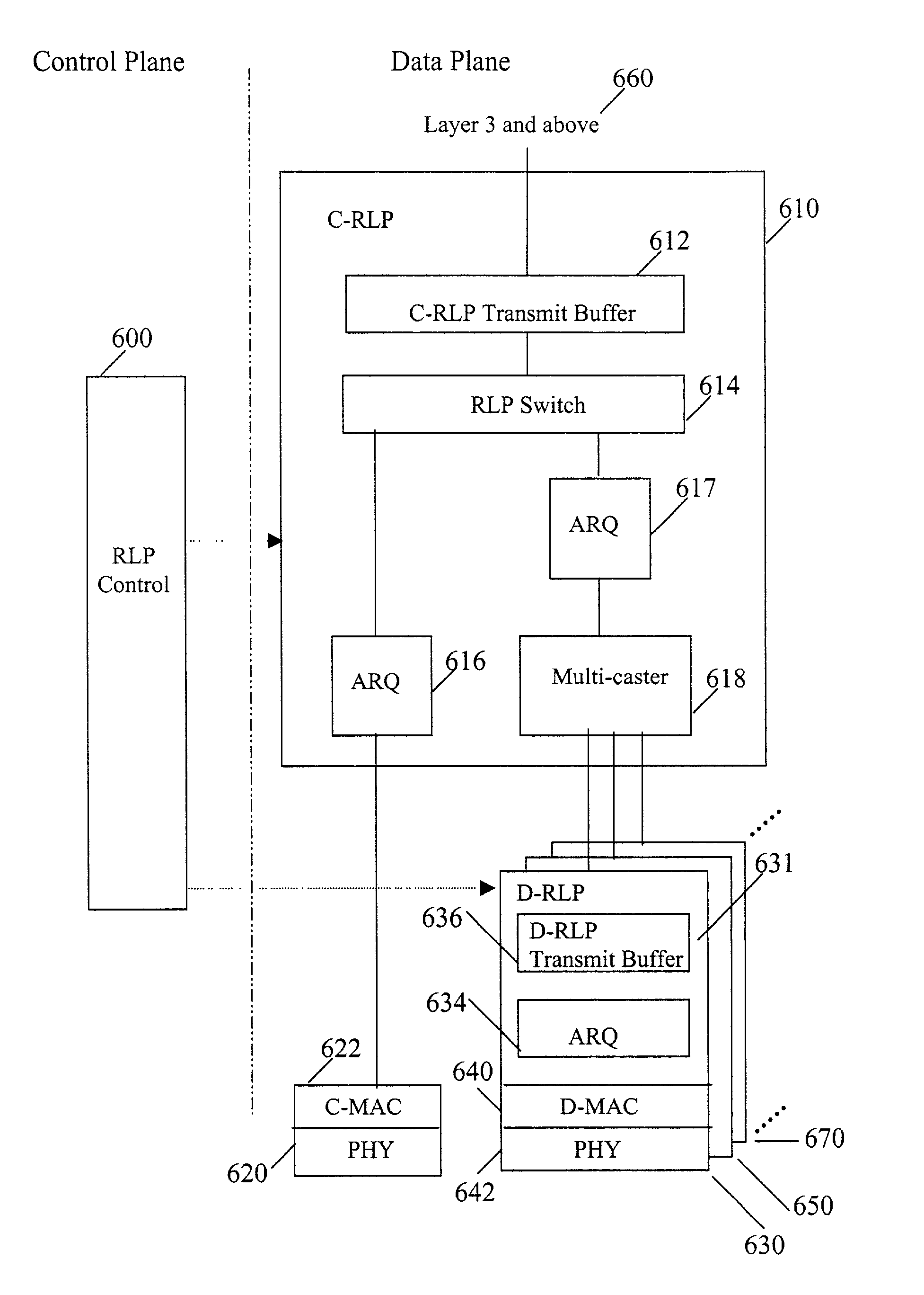
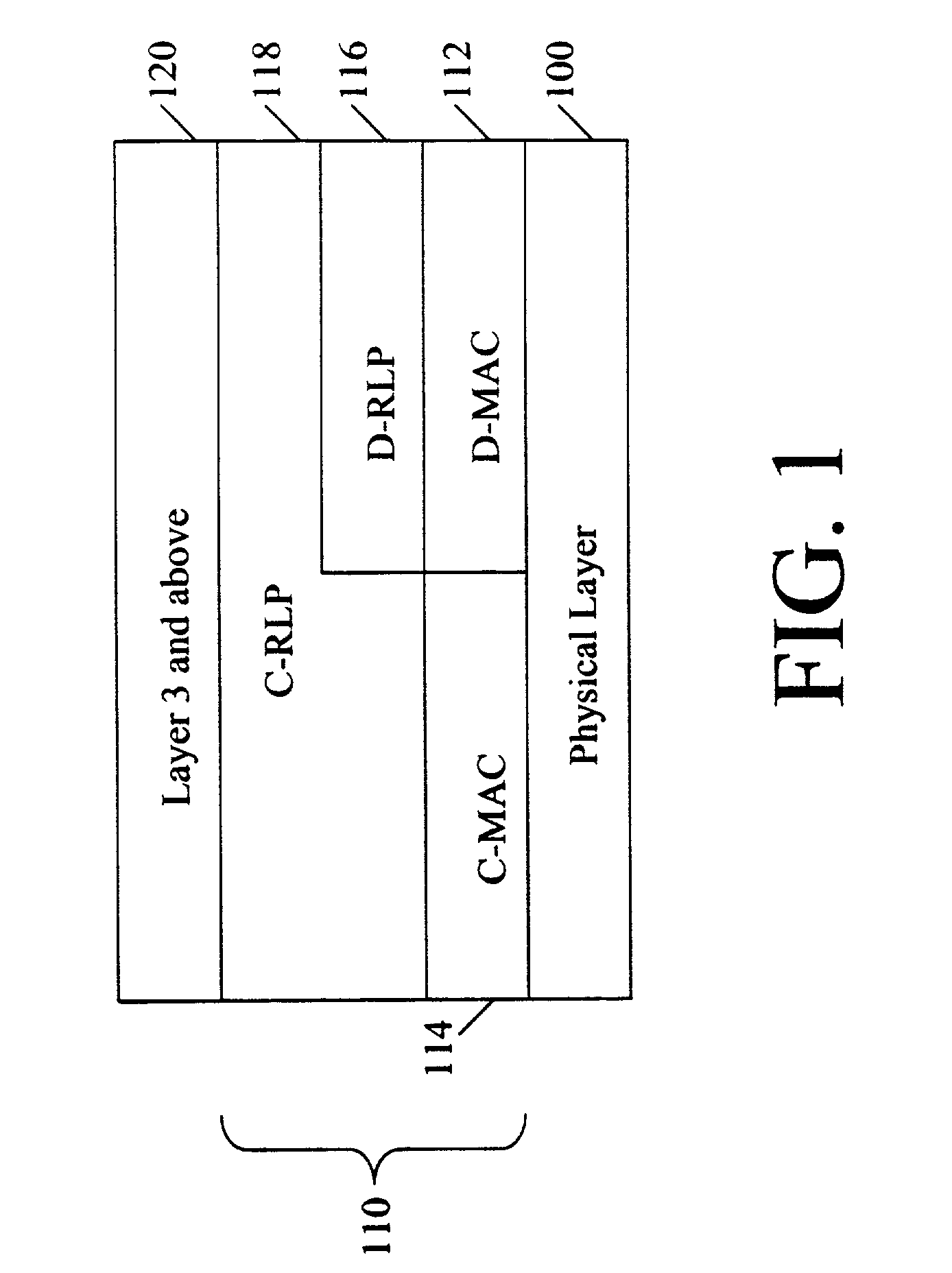
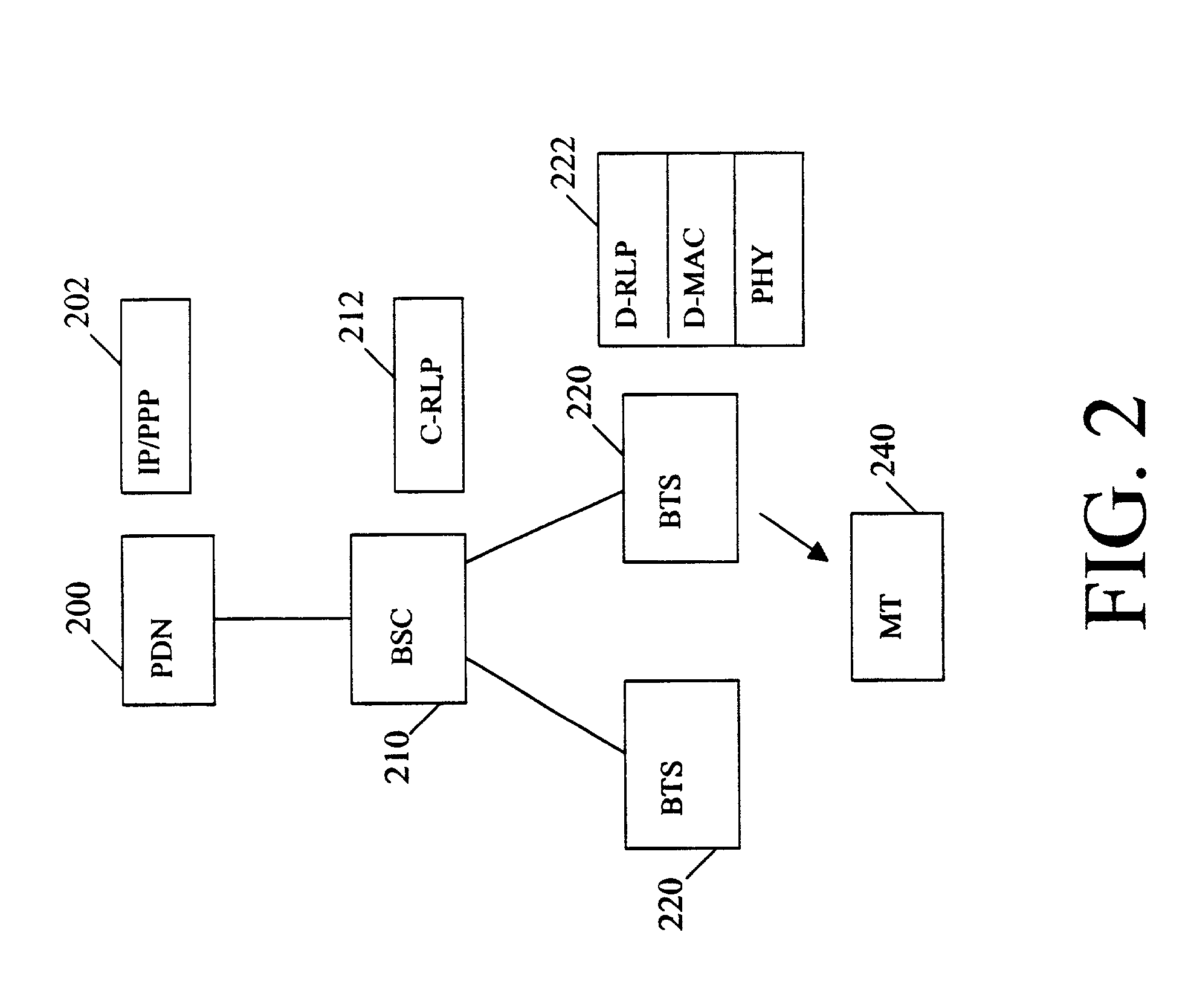
[0020]The present invention provides a wireless data network architecture that supports both centralized mode operation and distributed mode operation. In the centralized mode, all of the Open Systems Interconnection (OSI) reference model data link layer, also known as layer 2, protocol functions are implemented within the radio access control entity, such as at a base station controller (BSC) or similar network controller. In the distributed mode, some of the layer 2 protocol functions are implemented at the BSC or similar network controller, and some of the layer 2 protocol functions are implemented at the BTSs.

[0021]The data transmission to a mobile terminal may be dynamically switched from one of the modes to the other as a function of various implementation-specific triggers such as the data transmission rate, the mobility of the customer device and the type of user application. As an example, the distributed mode may be implemented when a data call is made to or received from ...


PUM


Abstract

A wireless data network architecture supports both centralized mode operation and distributed mode operation. In the centralized mode, all of the Open Systems Interconnection (OSI) reference model data link layer, also known as layer 2, protocol functions are implemented within the radio access network control entity, such as at a base station controller (BSC) or similar network controller, before the data packets are delivered to one or more base station transceiver subsystems (BTSs). In the distributed mode, some of the layer 2 protocol functions are implemented at the BSC or similar network controller, and some of the layer 2 protocol functions are implemented at the BTSs. The data transmission is dynamically switched from one of the modes to the other as a function of various implementation-specific triggers.

Description

RELATED APPLICATIONS[0001]This application claims the priority of U.S. Provisional Application No. 60 / 170,909, filed Dec. 15, 1999 and the priority of U.S. Provisional Application No. 60 / 176,985, filed Jan. 19, 2000.BACKGROUND OF THE INVENTION[0002]The present invention is directed to data networks and, more particularly, to wireless data networks for providing mobile terminals and other devices with high speed data services such as high speed Internet services.[0003]Wireless data networks are typically employed as an extension of a wired data network or in place of a wired data network to provide user access to networked data services. The wireless data networks reduce or eliminate the need for wired connections and thus permit fast setup of a data network as well as allow for simplified, low cost additions to and reconfiguration of the data network. The wireless data networks also facilitate the use of hand-held or notebook computers, personal digital assistants (PDA) or other han...

Claims


Application Information

Patent Timeline
IPC IPC(8): H04Q7/00H04J3/16H04J3/22H04L29/06H04L29/08
CPCH04L29/06H04L69/32H04L69/324H04L9/40H04L69/325H04W36/32
Inventor FONG, MO-HANWU, GENG
Owner ALCATEL LUCENT SAS
Why Eureka
Try Eureka