Optoelectronic transceiver having dual access to onboard diagnostics

a technology of onboard diagnostics and transceivers, applied in the direction of electromagnetic transmission, electromagnetic transceivers, electrical apparatus, etc., can solve the problems of transceivers that provide a uniform device architecture, few if any of these additional functions are implemented

Inactive Publication Date: 2006-12-12
II VI DELAWARE INC
View PDF101 Cites 36 Cited by
  • Summary
  • Abstract
  • Description
  • Claims
  • Application Information

AI Technical Summary

Benefits of technology

[0032]Accordingly, multiple controller ICs within the optoelectronic transceiver provide a remote host with separate access to diagnostic data on each controller IC. This allows hosts that are preconfigured differently to read different memory mapped locations on the different controller ICs to obtain the same diagnostic data. Furthermore, the interfaces in the first and second controller ICs may be configured to communicate using different protocols. This allows the same optoelectronic transceiver to be used with hosts that communicate using different protocols without any redesign or reconfiguration of the optoelectronic transceiver.

Problems solved by technology

Few if any of these additional functions are implemented in most transceivers, in part because of the cost of doing so.
However, to date there have not been any transceivers that provide a uniform device architecture that will support all of these functions, as well as additional functions not listed here, in a cost effective manner.

Method used


Image

  • Optoelectronic transceiver having dual access to onboard diagnostics
  • Optoelectronic transceiver having dual access to onboard diagnostics
  • Optoelectronic transceiver having dual access to onboard diagnostics

Examples


Embodiment Construction

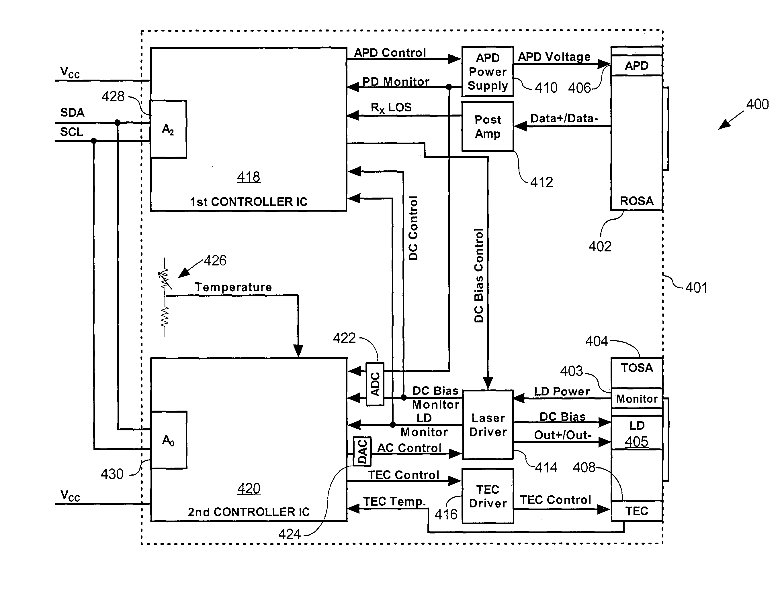
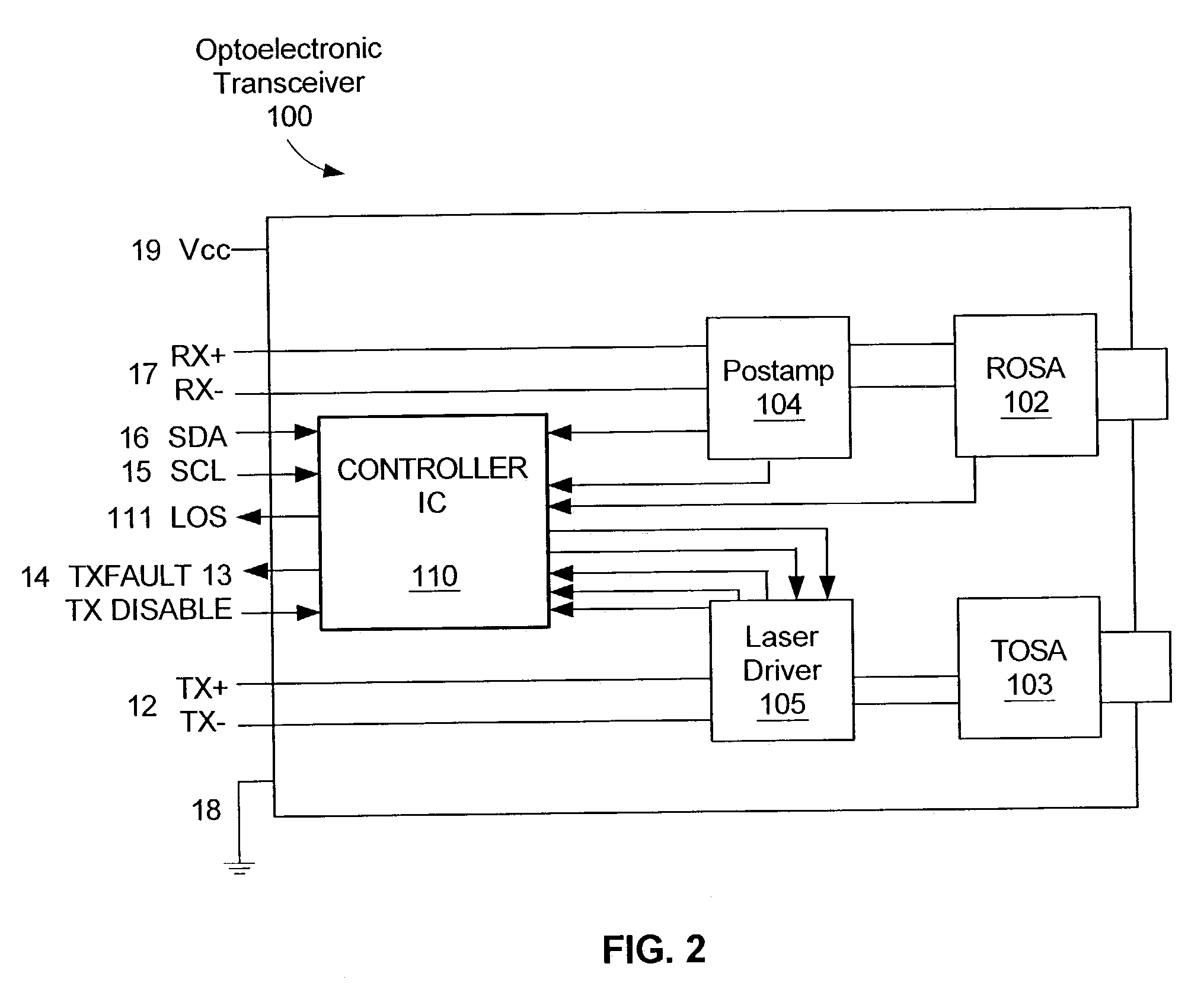
[0039]A transceiver 100 based on the present invention is shown in FIGS. 2 and 3. The transceiver 100 contains a Receiver Optical Subassembly (ROSA) 102 and Transmitter Optical Subassembly (TOSA) 103 along with associated post-amplifier 104 and laser driver 105 integrated circuits that communicate the high speed electrical signals to the outside world. In this case, however, all other control and setup functions are implemented with a third single-chip integrated circuit 110 called the controller IC.

[0040]The controller IC 110 handles all low speed communications with the end user. These include the standardized pin functions such as Loss of Received Signal (LOS) 111, Transmitter Fault Indication (TX FAULT) 14, and the Transmitter Disable Input (TXDIS) 13. The controller IC 110 has a two wire serial interface 121, also called the memory interface, for accessing memory mapped locations in the controller. Memory Map Tables 1, 2, 3 and 4, below, are an exemplary memory map for one embo...


PUM


Abstract

The optoelectronic transceiver includes first and second controller ICs. Each controller IC includes logic, a memory, an interface, and at least one input port. Each memory is configured to store digital diagnostic data and has a unique serial device address to allow a host access to each of these controller ICs separately and independently. At least some of the digital diagnostic data is common to both the first controller IC and the second controller IC. The inclusion of two controller ICs allows the same diagnostic data to be stored in completely different memory mapped locations. This allows hosts that are preconfigured differently to read different memory mapped locations on the different controller ICs to obtain the same diagnostic data.

Description

[0001]This application claims priority to and is a continuation-in-part of U.S. patent application Ser. No. 09 / 777,917, filed Feb. 5, 2001, which is hereby incorporated by reference.BACKGROUND OF THE INVENTION[0002]1. Field of the Invention[0003]The present invention relates generally to the field of optoelectronic transceivers and particularly to circuits used within the optoelectronic transceivers to accomplish control, setup, monitoring, and identification operations.[0004]2. Description of Related Art[0005]The two most basic electronic circuits within a fiber optic transceiver are the laser driver circuit, which accepts high speed digital data and electrically drives an LED or laser diode to create equivalent optical pulses, and the receiver circuit which takes relatively small signals from an optical detector and amplifies and limits them to create a uniform amplitude digital electronic output. In addition to, and sometimes in conjunction with these basic functions, there are a...

Claims


Application Information

Patent Timeline
Patent Type & Authority Patents(United States)
IPC IPC(8): H04B10/00H04B10/02H04B10/06H04B10/04H04B10/08H04B10/14H04B10/24H04B10/26H04B10/43H05K
CPCH04B10/0799H04B10/40H04B2210/08H04B10/6911
Inventor HOSKING, LUCY G.STEWART, JAMESHO, ANTHONY
Owner II VI DELAWARE INC
Why Eureka
Try Eureka