Sliding door assembly

a technology of sliding doors and assemblies, applied in the direction of mechanical actuation of burglar alarms, insect protection, instruments, etc., can solve the problems of high thermal conductivity of aluminum, condensation or ice formation on the interior surface of the sash or on the glass panel, and high heat loss of the sash formed of aluminum sections

Inactive Publication Date: 2006-12-19
PORTES PATIO RESIVER
View PDF23 Cites 32 Cited by
  • Summary
  • Abstract
  • Description
  • Claims
  • Application Information

AI Technical Summary

Benefits of technology

[0010]It is a still further feature of the present invention to provide a corner connector for improving a connection between elongated members forming a sash.

Problems solved by technology

However, a great disadvantage of the use of aluminum extruded sections for sliding doors is the high thermal conductivity of aluminum.
In a cold climate, a sliding door sash solely consisting of aluminum sections can easily become very cold and thus cause condensation or ice formation on an interior surface of the sash or on the glass panel.
Furthermore, the high thermal conductivity of aluminum causes high heat losses to sashes formed of aluminum sections.
However, where sliding doors are composed of numerous sections and the sliding doors are subjected to great temperature differentials between interior and exterior temperatures, the difference in expansion of the various components of a sliding door can result in the deformation thereof.
Furthermore, differences in thermal expansion of components can cause damage to the seals of the sliding door and result in water infiltration and air leaks, and create problems in the sliding of the door with respect to the frame.
Also, having numerous sections involves a greater number of components and requires more manpower for the assembly thereof because of the increased complexity.

Method used


Image

  • Sliding door assembly
  • Sliding door assembly
  • Sliding door assembly

Examples


Embodiment Construction

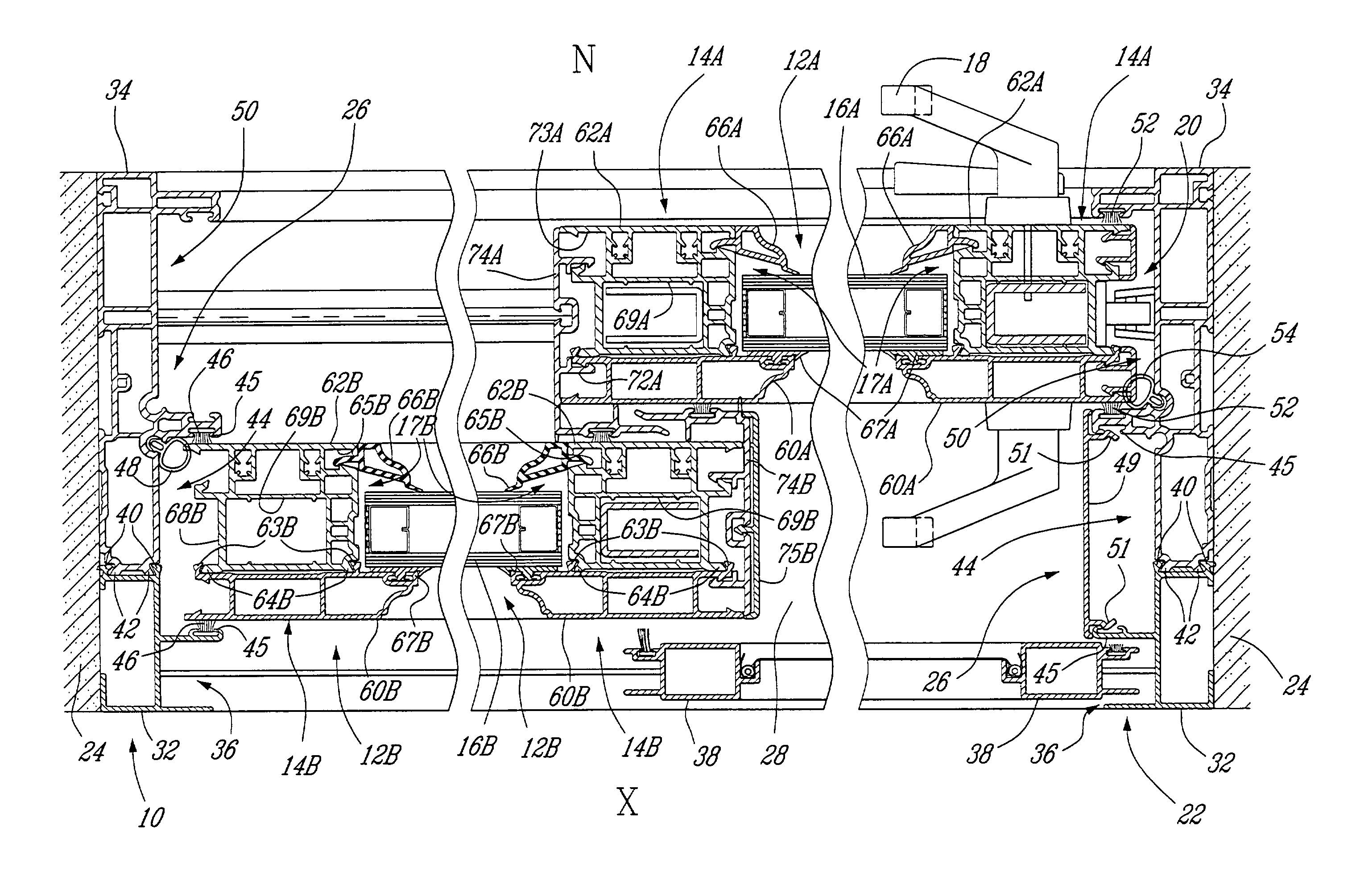
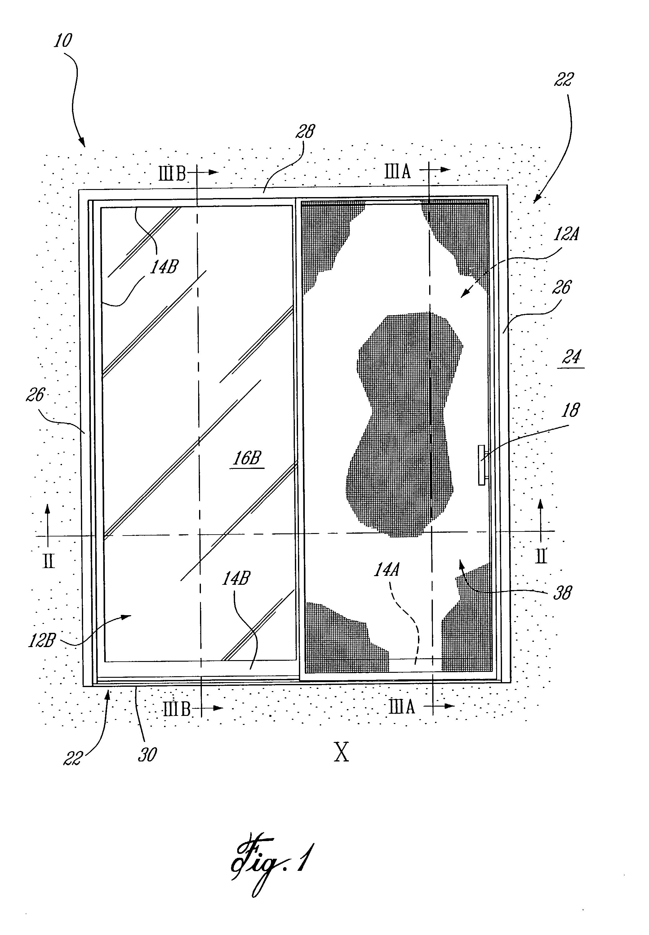
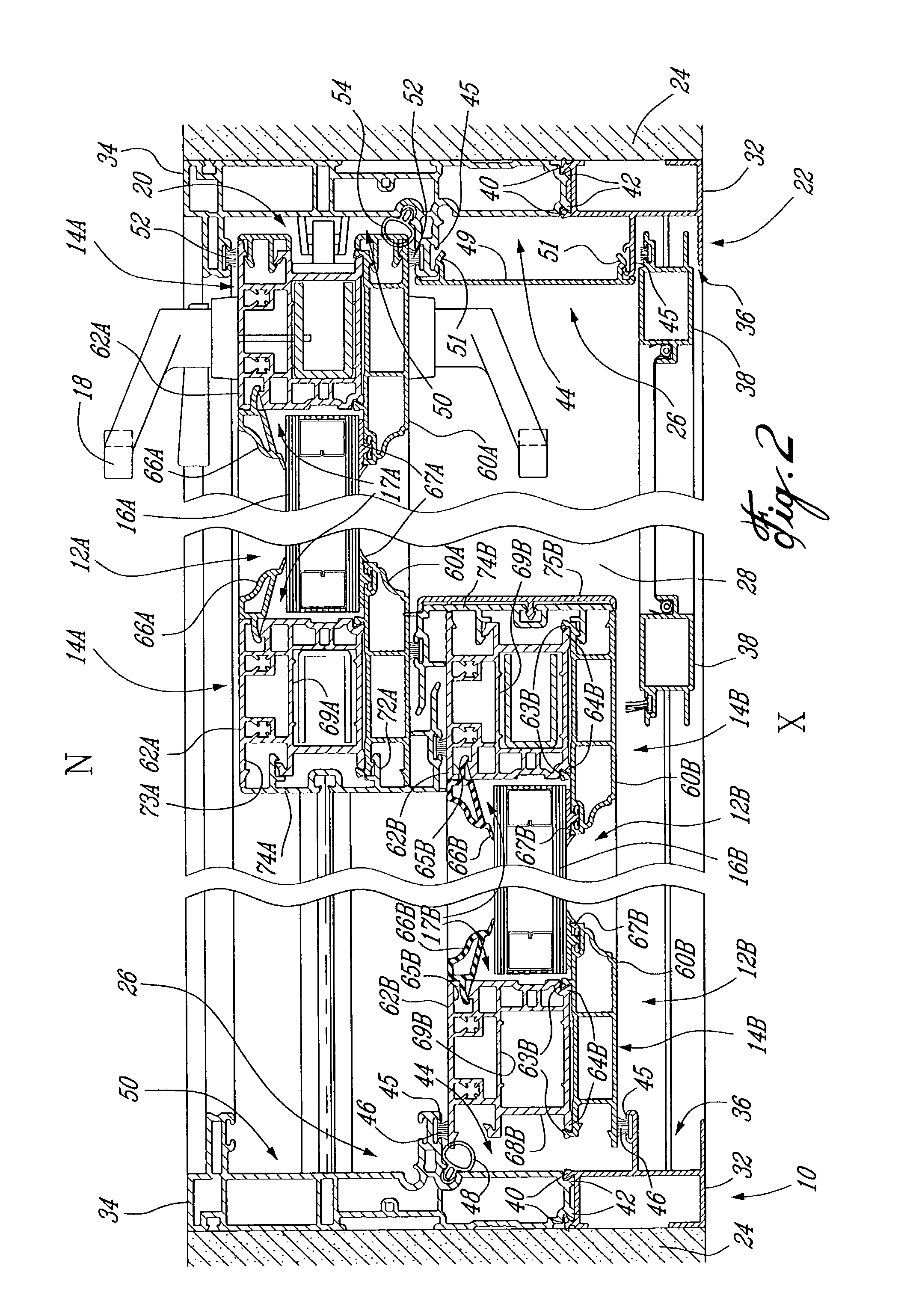
[0022]Referring to the drawings, and more particularly to FIG. 1, a sliding door assembly constructed in accordance with the present invention is generally shown at 10. The sliding door assembly 10 has a sliding door 12A, shown behind a screen stile 38, and a fixed door 12B. The sliding door 12A and the fixed door 12B generally comprise the same parts. For simplicity purposes, reference will be made to like elements of the sliding door 12A and the fixed door 12B without the letters “A” and “B” affixed thereto. However, the reference numerals on the drawings will have letters affixed thereto, namely “A” for parts of the sliding door 12A and “B” for parts of the fixed door 12B. The doors 12 typically consist of a sash 14 supporting a glass panel 16. The sliding door 12A has a handle 18 on an interior and an exterior side thereof, as best shown in FIG. 2. The handle 18 incorporates a locking system 20 that will lock the sliding door 12A to a frame 22 of the sliding door assembly 10.

[00...


PUM


Abstract

A door assembly of the type having a frame mounted to a wall. The frame comprises a head portion, opposed vertical jamb portions and a sill portion. Doors are provided in the frame. A door in the frame is displaceable between an open position and a closed position. The doors comprise a sash portion supporting a see-through panel. Each of the head portion, the jamb portion, the sill portion, and the sash portion of the door has one external cladding and one internal cladding. The external cladding and the internal cladding are detachably connected to one another, such that only the external cladding is exposed to an exterior of the door assembly and only the internal cladding is exposed to an interior of the door assembly when the door is in the closed position. A method for interconnecting two hollow elongated extruded sections of the door sash is also provided.

Description

TECHNICAL FIELD[0001]The present invention generally relates to sliding door assemblies and, more particularly, to a configuration of sliding door components, wherein the external cladding is formed of common components, as well as the internal cladding.BACKGROUND ART[0002]Sliding door assemblies are typically known as doors having a sash supporting a glass panel that covers a substantial portion of the door, with the sliding door slidingly mounted to a frame so as to slide with respect to the frame. Sliding door assemblies often include a sliding door and a fixed door mounted to a frame consisting of a head, a sill and jambs.[0003]Aluminum is an elegant, light and resistant material that is readily extruded into complex sections, whereby it is a well suited material for at least an external cladding of a sliding door. However, a great disadvantage of the use of aluminum extruded sections for sliding doors is the high thermal conductivity of aluminum. Aluminum is an excellent heat c...

Claims


Application Information

Patent Timeline
Patent Type & Authority Patents(United States)
IPC IPC(8): E06B1/04E06B3/46G08B13/08
CPCE06B3/26301E06B3/26347E06B3/301E06B3/4618E06B9/52
Inventor KOBAYASHI, TETSUYAGILBERT, ERIC
Owner PORTES PATIO RESIVER
Why Eureka
Try Eureka