
Reading lamp for aircraft cabins

a technology for reading lamps and aircraft cabins, applied in the field of reading lamps, can solve the problems of difficult adjustment, large installation volume in the overhead area, and often not being able to install, and achieve the effect of small space and convenient installation

Active Publication Date: 2006-12-19
AIRBUS OPERATIONS GMBH
View PDF11 Cites 14 Cited by
  • Summary
  • Abstract
  • Description
  • Claims
  • Application Information

AI Technical Summary

Benefits of technology

The invention is a light projecting reading lamp with a horizontal optical axis that can be adjusted to direct light onto a passenger's seat. The adjustment can be made by a passenger or a flight attendant using remote control. The lamp has a low structural height and can be easily installed in different seating layouts. The adjustable direction of the light makes it compatible with different seating layouts. The invention also allows for automatic adjustment of the light direction based on the position of the passenger seat.

Problems solved by technology

However, for making conventional lamps adjustable so that their light output can be directed to various seat row positions, a substantial installation volume is required in the overhead area, due to the desired small light exit area because for this purpose the tilting axes for the adjustment of the light direction cannot be located in the geometric center of gravity of the particular reading lamp.
Rather, the tilting axis needs to be located very close to the light exit or front face or cover of the reading lamp, which makes the adjustment more difficult.
While it is desirable that each passenger should be able to individually adjust the reading lamp or light allocated to his seat, this is frequently not possible due to the constructive layout of the overhead supply channel in which these reading lamps or lights are installed.
Thus, providing each individual passenger with the comfort of being able to adjust the respective reading lamp is frequently not realizable with conventional reading lights.

Method used


Image

  • Reading lamp for aircraft cabins
  • Reading lamp for aircraft cabins
  • Reading lamp for aircraft cabins

Examples


Embodiment Construction

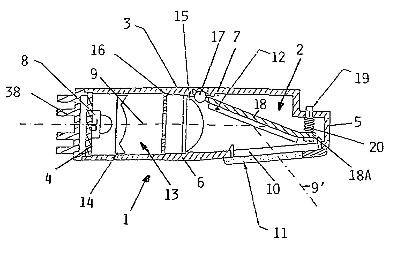
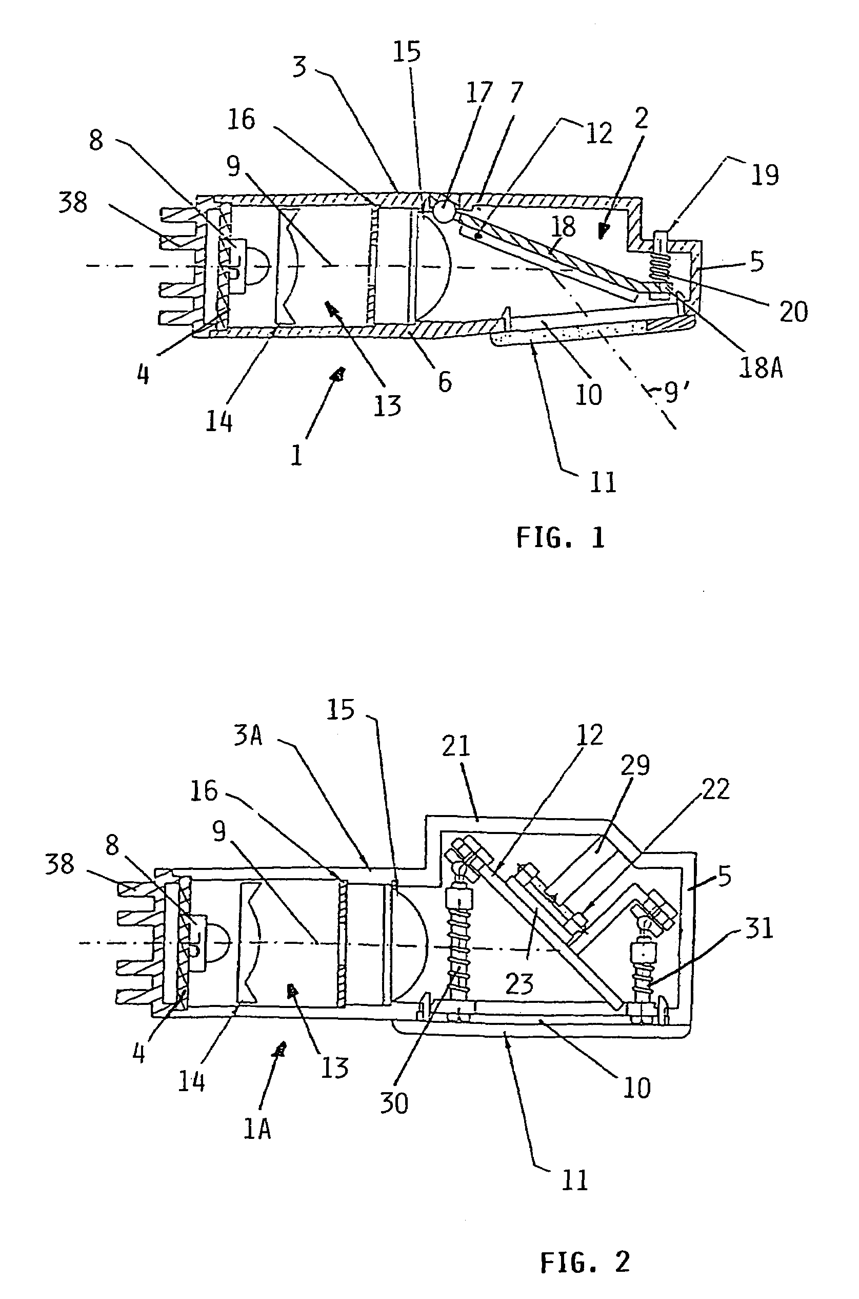
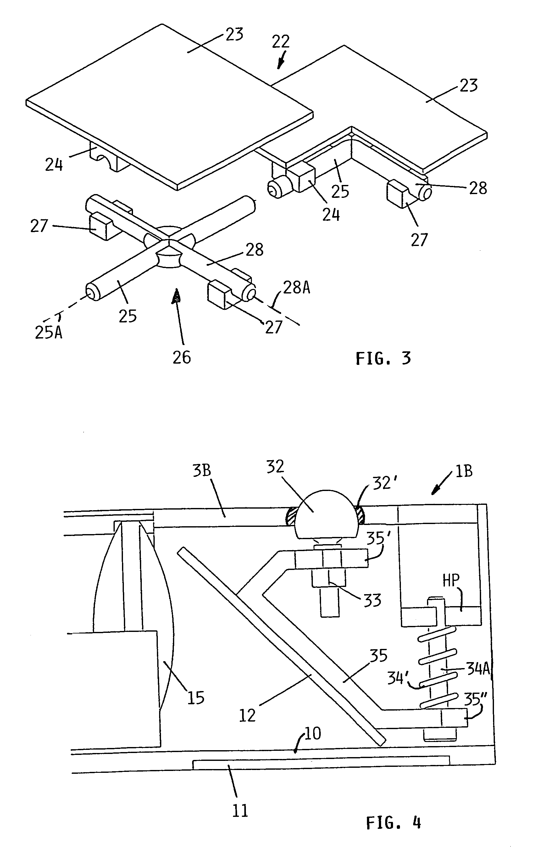
[0024]FIG. 1 shows a reading lamp 1 having an adjustable optical deflector 2 secured in a mounting element 3 in the form of a housing as shown. Alternatively, the mounting element 3 could be a mounting bracket, a mounting support or a mounting plate, or the like. The housing 3 preferably has a rectangular or square cross section with a longitudinal housing axis that preferably coincides with an optical axis 9 of a light source 8 that is secured to a first end 4 of the housing 3. The optical axis 9 extends toward an opposite end 5 of the housing 3. Longitudinal side walls 6 and 7 complete the housing 3. When the reading lamp 1 is installed in the overhead area of an aircraft cabin, the optical axis 9 extends substantially horizontally as explained above. In the area next to the opposite housing end 5, the side wall 6 is provided with a light exit opening 10. This exit opening 10 is preferably closed by a transparent cover 11 such as a plane pane or a converging lens. The optical defl...


PUM


Abstract

A reading lamp for an aircraft cabin, particularly installed above a passenger seat, has a light source emitting a light beam with an optical axis extending substantially horizontally so that a light beam can be deflected by an optical deflector such as a mirror, to a passenger seat. This orientation of the light source provides a compact construction of the reading lamp. Preferably the deflector position is adjustable relative to the optical axis.

Description

PRIORITY CLAIM[0001]This application is based on and claims the priority under 35 U.S.C. §119 of German Patent Application 103 07 147.4, filed on Feb. 20, 2003, the entire disclosure of which is incorporated herein by reference.FIELD OF THE INVENTION[0002]The invention relates to a reading lamp (also generally called a reading light) for a passenger cabin, particularly in an aircraft. Such reading lights are normally installed above a passenger seat and include at least one light source, preferably of the LED type or of a miniature halogen type.BACKGROUND INFORMATION[0003]Modern passenger aircraft cabins are equipped with reading lamps or lights installed above each passenger seat in the ceiling area. Such lamps provide an individually switchable or controllable illumination for the passenger seated in the respective passenger seat area. It is typical for such lamps to use either light emitting diodes or miniature halogen lamps as the light source. Generally, the number of reading l...

Claims


Application Information

Patent Timeline
Patent Type & Authority Patents(United States)
IPC IPC(8): B64D47/02F21V21/00B60Q3/02F21V14/04F21V17/02
CPCB60Q3/0253B60Q3/0286F21V7/0008F21V13/12F21V17/02F21V14/04F21V29/74F21Y2101/02F21V5/008F21V7/05F21Y2115/10B60Q3/44B60Q3/76
Inventor KOHLMEIER-BECKMANN, CARSTENHEYM, DETLEF
Owner AIRBUS OPERATIONS GMBH
Learn More