Power transmission apparatus for automobile

a technology for power transmission and automobiles, applied in hybrid vehicles, gearing, vehicle sub-unit features, etc., can solve the problems of difficult to reduce fuel efficiency or mileage, and the electric motor(s) to escape, so as to reduce mileage or fuel efficiency

Inactive Publication Date: 2006-12-19
HITACHI LTD
View PDF17 Cites 53 Cited by
  • Summary
  • Abstract
  • Description
  • Claims
  • Application Information

AI Technical Summary

Benefits of technology

[0006]Therefore, according to the present invention, by taking the above into the consideration, an object is to provide a control unit for a motive power transmission apparatus, with which various driving modes can be achieved and the ele...

Problems solved by technology

However, with such the structure of the transmission apparatus as mentioned above, since required torque of the electric motor(s) is large during the gear-shiftin...

Method used


Image

  • Power transmission apparatus for automobile
  • Power transmission apparatus for automobile
  • Power transmission apparatus for automobile

Examples


Embodiment Construction

[0030]Hereinafter, embodiments according to the present invention will be fully explained by referring to the attached drawings.

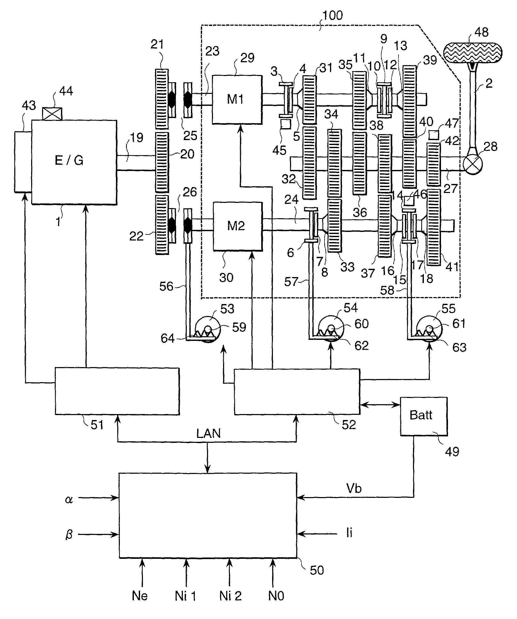
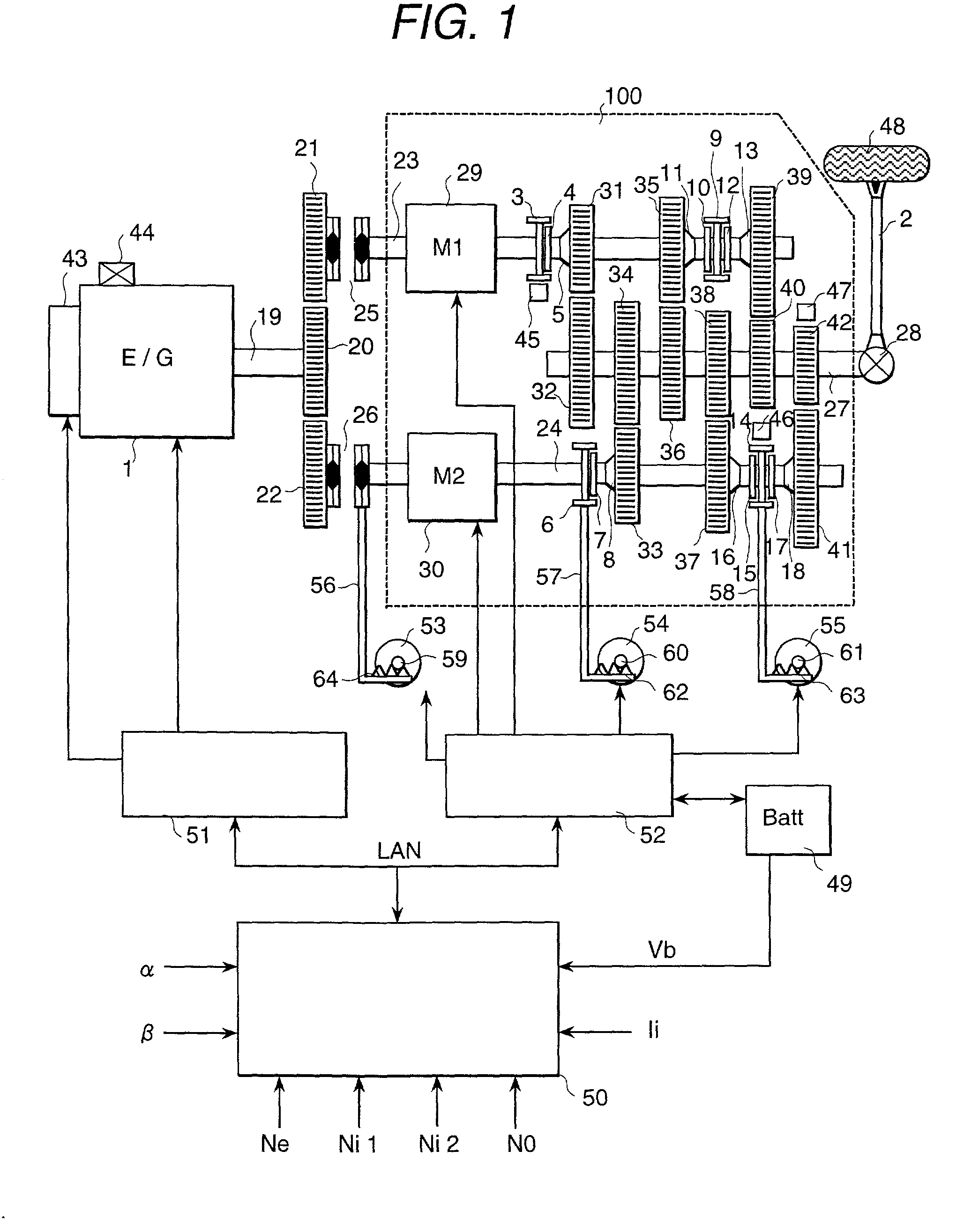
[0031]FIG. 1 shows the structure of an automobile system, according to an embodiment of the present invention.

[0032]Within an engine 1, an amount of suction air is controlled by means of an electronic control throttle 43 provided in a suction tube or conduit (not shown in the figure), and an amount of fuel fitting to the air amount is injected from a fuel injector(s) (not shown in the figure). Also, ignition timing is determined upon basis of signals, such as, an air-fuel ratio, which is determined by the amounts of air and fuel mentioned above, and an engine rotating speed Ne, which is measured from an engine rotating speed sensor 44, thereby the ignition is conducted by means of an ignition apparatus (not shown in the figure). As the fuel injection apparatus, there is one of an intake port injection method, in which the fuel is injected into an air intake...


PUM


Abstract

In a control unit for an automobile power transmission apparatus which includes a gear-type transmission and several of the motors are controlled so as to suppress thrust or push-up on the torque of the output shaft of the transmission due to inertia torque or to suppress draw or pull-in on the output shaft.

Description

BACKGROUND OF THE INVENTION[0001]The present invention relates to the structure of a motive power transmission system, comprising an engine, electric motors and a gear-type transmission therein, and in particular, relates to a power transmission apparatus for obtaining both reduction of fuel efficiency (or mileage) and drivability through small-sizing and weight-lightening of the motive power transmission system.[0002]Such the power transmission apparatus, according to the conventional art, for achieving an improvement of transmission efficiency in the motive power transmission system, as well as, the drivability thereof, is already known and described in Japanese Patent Laying-Open No. Hei 11-313404 (1999), for example.[0003]In this publication is described the power transmission apparatus for use in an automobile, in which an input shaft of the gear-type transmission is connected to an electric power generator or alternator while an output shaft thereof is connected to an electric...

Claims


Application Information

Patent Timeline
IPC IPC(8): B60W10/02B60K1/02B60K6/38B60K6/48B60K6/547B60K17/08B60W10/10B60W30/18F16H3/00F16H3/089F16H3/093F16H3/097F16H3/12F16H61/688
CPCB60K6/48B60K6/547B60W10/02B60W10/06B60W10/11B60W10/113B60W30/19F16H3/006F16H3/126B60K6/442B60K6/38B60K1/02Y10T477/26B60K2006/541B60K2741/225B60Y2400/428F16H3/089F16H3/093F16H61/688F16H2061/0422F16H2061/0433F16H2200/0052F16H2306/44F16H2306/52Y02T10/6221Y02T10/6234Y10T477/27Y10T74/19051Y10T74/19223Y10T74/19014Y10T74/19056B60W10/10B60W30/1819Y02T10/62B60W30/18063
Inventor SAKAMOTO, HIROSHIMINOWA, TOSHIMICHIOKADA, TAKASHIKAYANO, MITSUOOCHI, TATSUYAKUROIWA, HIROSHIIBAMOTO, MASAHIKO
Owner HITACHI LTD
Why Eureka
Try Eureka