Reaction device for forming equipment

a technology of forming equipment and reaction device, which is applied in the direction of shock absorbers, forging/pressing/hammering apparatus, forging/hammering/pressing machines, etc., can solve the problems of not being suited for other forming equipment or other applications, and achieve convenient servicing of the lifter, convenient replacement or replacement, and small size

Active Publication Date: 2006-12-26
DIEBOLT INT
View PDF2 Cites 42 Cited by
  • Summary
  • Abstract
  • Description
  • Claims
  • Application Information

AI Technical Summary

Benefits of technology

[0006]Some potential objects, features and advantages of the lifter assembly set forth herein include provide a modular lifter assembly that is readily usable with a wide range of forming equipment, readily permits use of common components among lifters of different configuration and construction, can be easily serviced and its components replaced as needed, can be used in a wide range of applications having different size and force requirements, is readily adaptable to a wide range of lift bar configurations, and is of relatively simple design, economical manufacture and assembly, is robust, durable, reliable and in service has a long and useful life. Of course, an apparatus embodying the present invention may achieve, none, some, all or different objects, features or advantages than set forth with regard to the exemplary embodiments disclosed herein.

Problems solved by technology

Accordingly, the lifters are custom designed for a particular application and are not suited for use in other forming equipment or other applications.

Method used


Image

  • Reaction device for forming equipment
  • Reaction device for forming equipment
  • Reaction device for forming equipment

Examples


Embodiment Construction

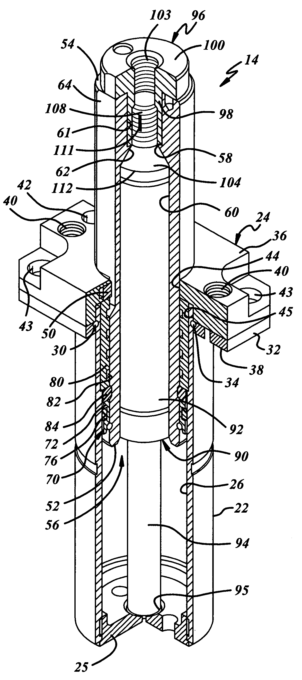
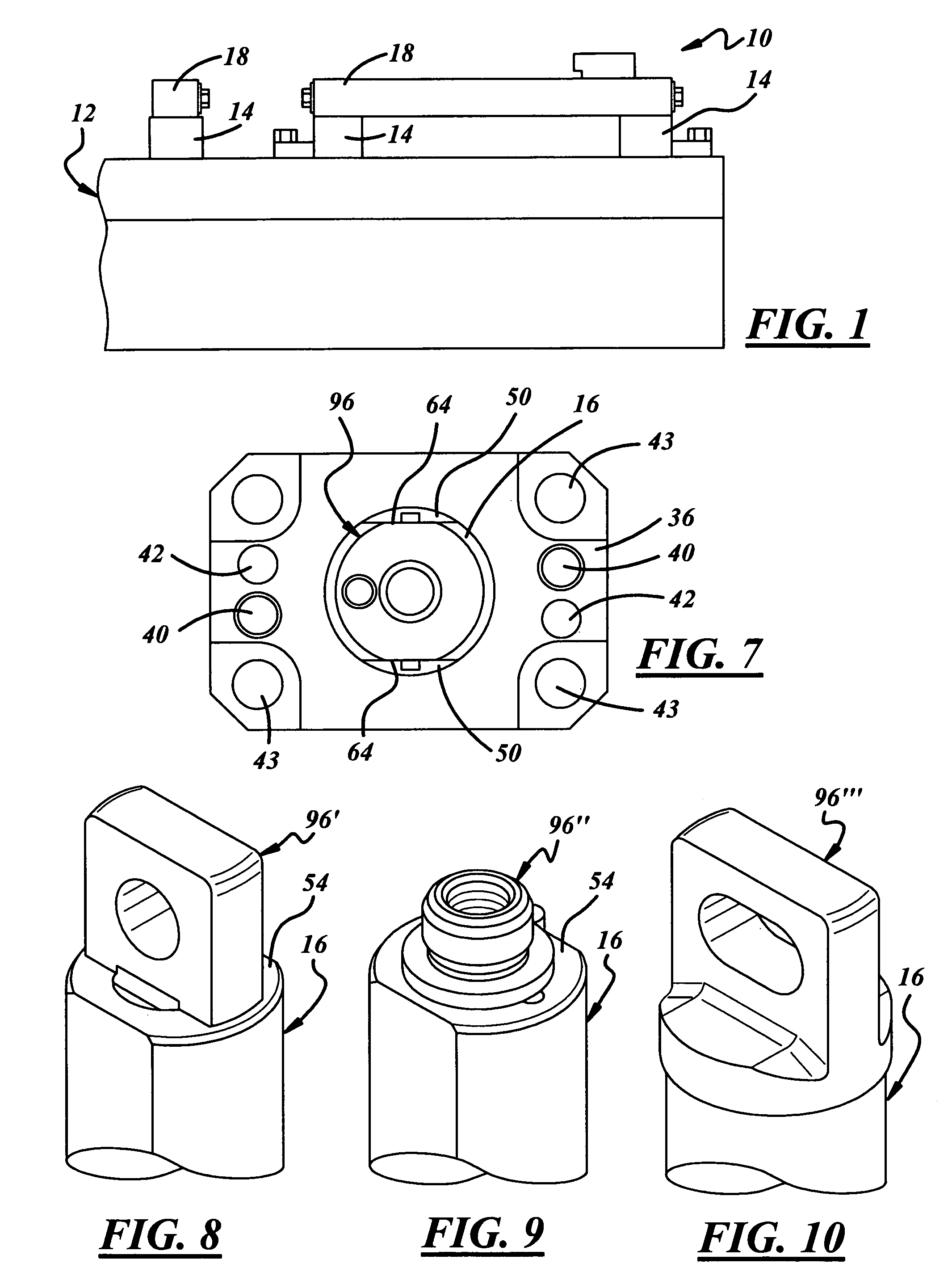
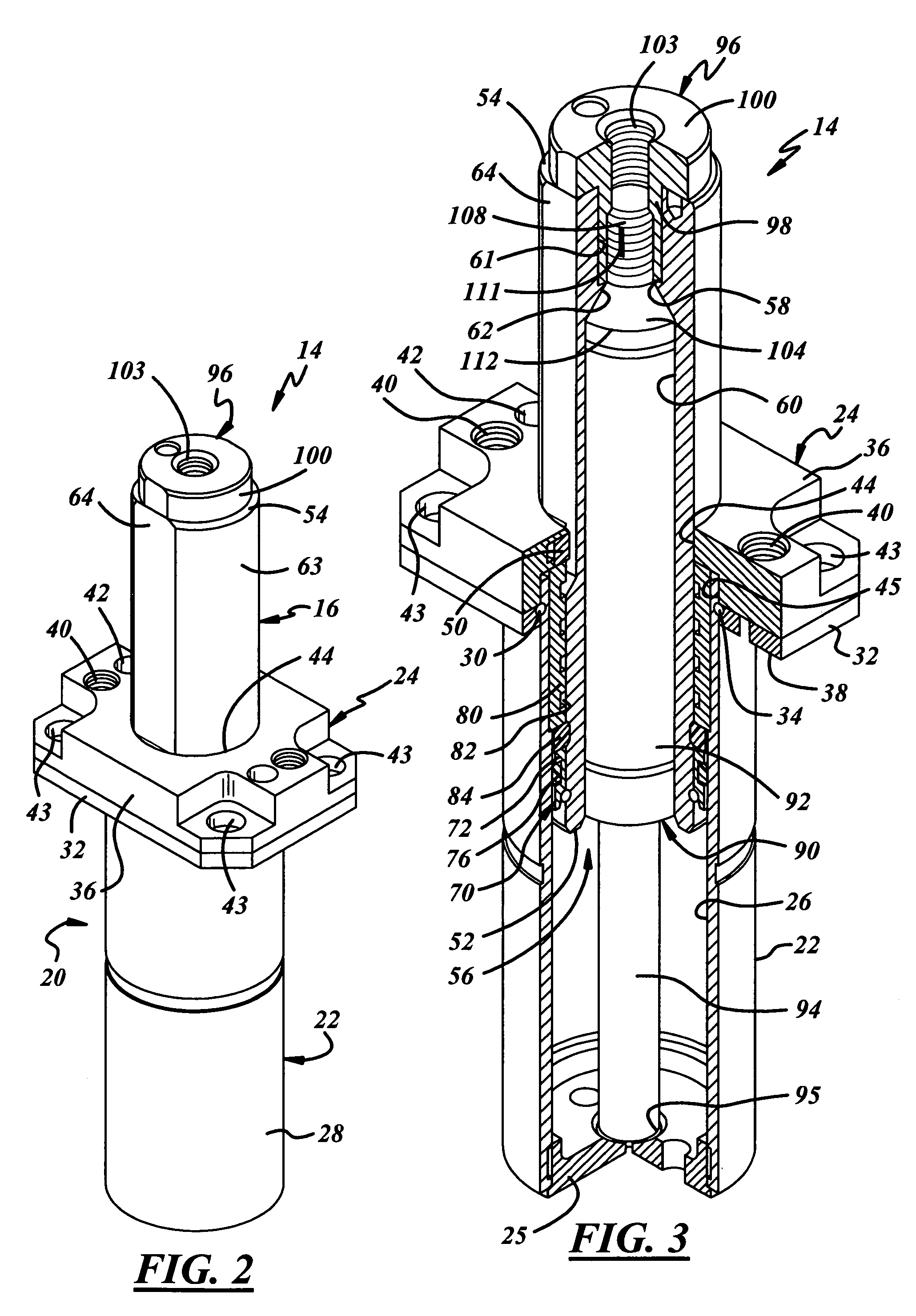
[0018]Referring in more detail to the drawings, FIG. 1 illustrates a portion of a progressive die assembly 10 for forming coil feed stock. The die 10 includes a bed 12 to which a plurality of reaction devices such as gas spring lifters 14 are mounted. The lifters 14 include rods 16 (FIG. 2) yieldably biased to an extended position away from the bed 12 and connected adjacent their free ends to a lift bar 18 which spans and interconnects the free ends of adjacent lift rods 16. The lift bar 18 supports, retains or is otherwise associated with the feed stock as the stock progresses through the forming dies 10, in known manner.

[0019]As best shown in FIGS. 2–4, one presently preferred implementation of the lifters 14 is of modular design and readily adaptable to a wide range of applications and forming dies. The lifter 14 includes a housing 20 that has a cylindrical casing 22 carried by and attached to a mount 24. The housing 20 preferably also includes an end cap or base 25 carried by th...


PUM

PropertyMeasurementUnit
pressureaaaaaaaaaa
outer diameteraaaaaaaaaa

Abstract

A reaction device for forming equipment includes a housing having a mount adapted to be connected to a forming die and a casing carried by the mount. A lift rod is disposed at least partially on the housing for movement relative to the house between extended and retracted positions. The lift rod has a first end disposed in the housing, a second end and a passage extending through the lift rod between its ends. An adapter is connected to the lift rod within the passage and is adapted to be coupled to a lift bar of the forming equipment. A biasing member is disposed between the lift rod and the housing to yieldably bias the lift rod to its extended position.

Description

FIELD OF THE INVENTION[0001]This invention relates generally to forming equipment and more particularly to a reaction device for use with forming equipment.BACKGROUND OF THE INVENTION[0002]Gas springs commonly are used in various implementations in forming equipment to provide a moveable component or support of a forming die or a workpiece with a yielding force or a return force. For example, in a binder ring implementation, a gas spring provides a yielding force against a binder ring of a forming die to hold a metal workpiece while another part of the forming die forms, cuts, stretches, or bends the workpiece. In a lifter implementation, the gas spring provides a yielding force and return force to lift a workpiece off a surface of the forming die or to otherwise maintain control of the workpiece. Of course, various springs including gas springs can be used in a wide range of other implementations.[0003]In a lifter implementation, a biasing member such as a gas spring is designed fo...

Claims


Application Information

Patent Timeline
Patent Type & Authority Patents(United States)
IPC IPC(8): B21D45/00
CPCB21D24/02F16F9/0218
Inventor COTTER, JONATHAN P.
Owner DIEBOLT INT
Why Eureka
Try Eureka