

Gas bag for a side impact protection device
- Summary
- Abstract
- Description
- Claims
- Application Information
AI Technical Summary
Benefits of technology
Problems solved by technology
Method used
Image

Examples
Embodiment Construction
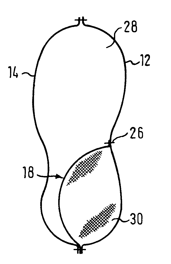
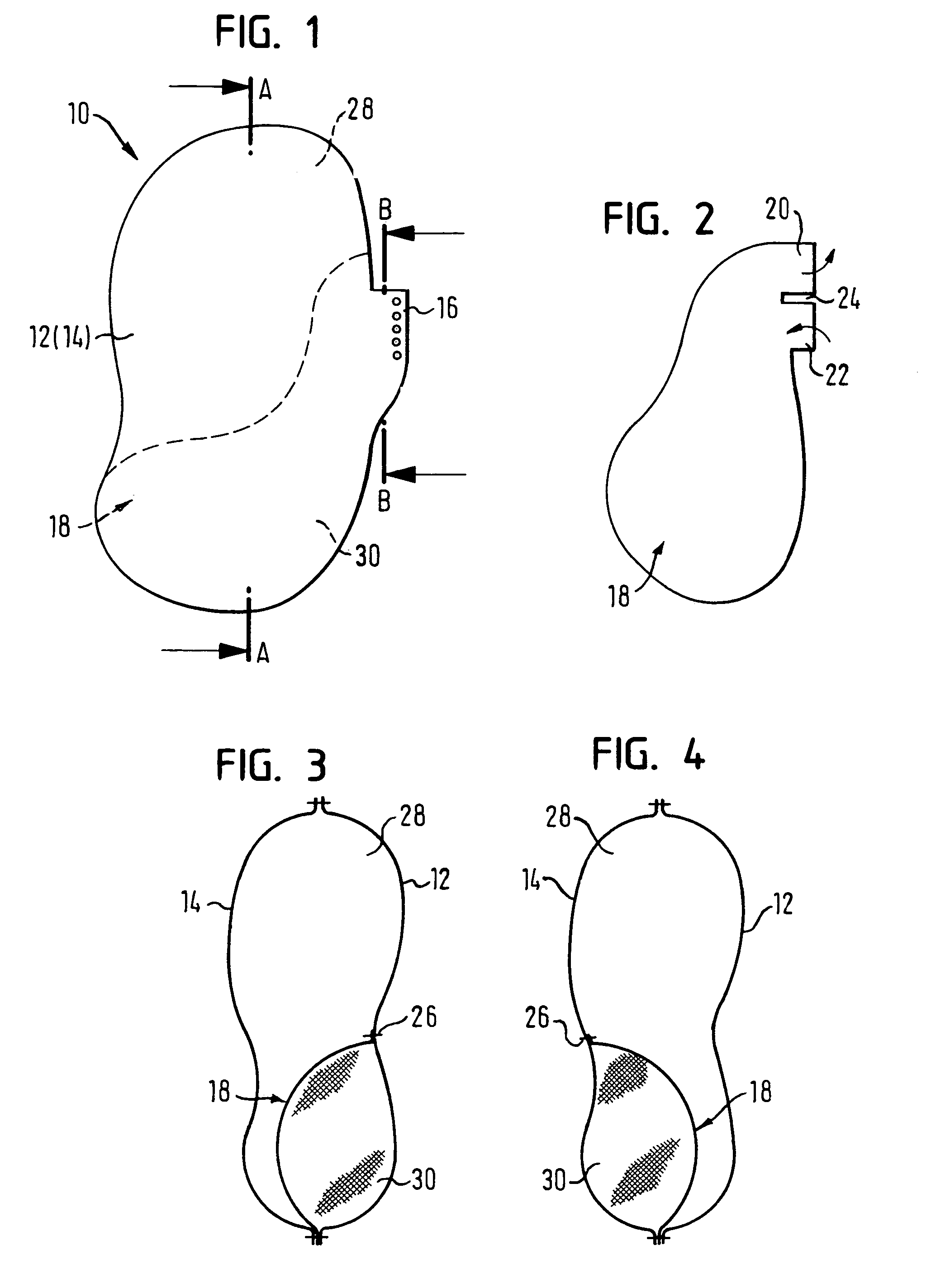
[0014]The gas bag 10 illustrated in FIG. 1 is a component of a gas bag module of a side impact protection device for a vehicle occupant, housed for example in a seat or in a door lining of a vehicle. The gas bag 10 is filled by means of a compressed gas source (not shown) and unfolds between the vehicle occupant and the door lining.
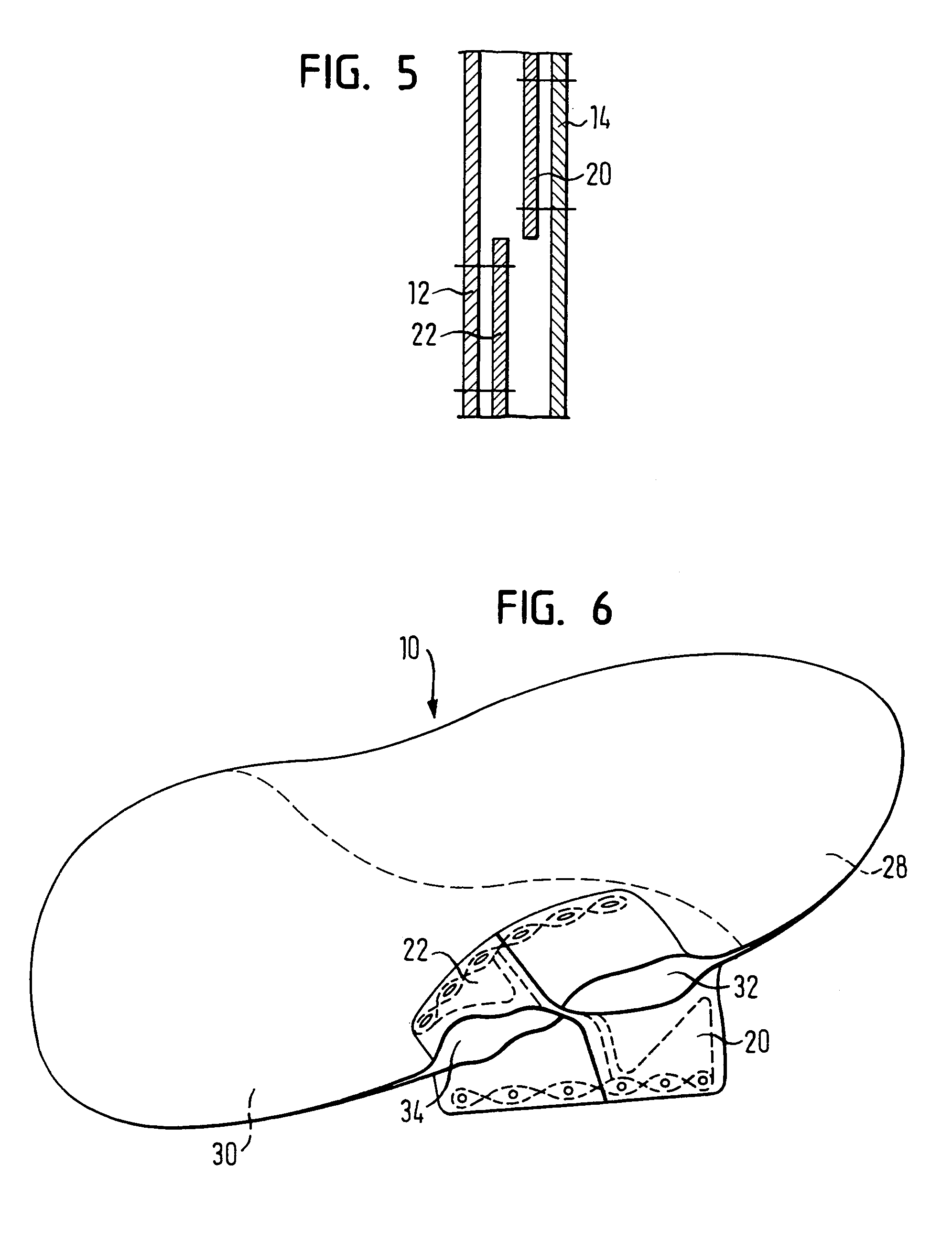
[0015]The gas bag 10 is formed from two congruent covering layers 12, 14, of which only the covering layer 12 facing the occupant is to be seen in FIG. 1. The gas bag 10 has an inflation opening 16 which is described later in further detail. Between the two covering layers 12, 14 an additional fabric layer 18 is arranged, which is illustrated separately in FIG. 2. The fabric layer 18, the contour of which coincides in particular in the lower region with that of the covering layers 12, 14, has in the region of the inflation opening an upper flap 20 and a lower flap 22, which are separated from each other by a slot 24. With the exception of one of the two f...
PUM
 Abstract
Description
Claims
Application Information