Fixed type constant velocity joint and method of producing the same

a constant velocity joint, fixed technology, applied in the direction of yielding couplings, rotary machine parts, couplings, etc., can solve the problems of reducing the torque load capacity, the torque load capacity of the constant velocity joint becomes smaller, and the fear of increasing the heat generation rate, so as to achieve the effect of reducing the size of the constant velocity join

Inactive Publication Date: 2006-12-26
NTN CORP
View PDF14 Cites 3 Cited by
  • Summary
  • Abstract
  • Description
  • Claims
  • Application Information

AI Technical Summary

Benefits of technology

[0012]It is an object of the present invention to be capable of securing a sufficient torque load capacity, maintaining the constant velocity property, and facilitating the assembling of components consisting of a joint outer ring, a cage, balls and a joint inner ring.
[0017]In the fixed type constant velocity joint according to the invention, in assembling the components consisting of a joint outer ring, a cage, balls and a joint inner ring, first, the cage is inserted through the front open end of the joint outer ring to assume its normal position, whereupon all of the torque transmitting balls are inserted into the cage. Then, in incorporating the joint inner ring, the joint inner ring can be inserted into the cage through the rear open end of the joint outer ring to assume its normal position since the rear open end of the joint outer ring has an inner diameter larger than the outer diameter of the joint inner ring and since a surface having a shape capable of allowing the axial movement of the joint inner ring, for example, an inner cylindrical surface is formed on the rear side of the cage spaced from the axial center of the inner diameter surface of the cage; thus, the assembling of the components can be simplified.
[0018]With this fixed type constant velocity joint, the construction in which the outer spherical surface is formed to extend to the rear of the joint inner ring while the concave spherical surface is formed in the end surface of a receiving section located rearwardly of said joint inner ring, and the concave spherical surface of the receiving section axially supports the outer spherical surface of said joint inner ring, results in the inner cylindrical surface of the cage radially supporting the outer spherical surface of the joint inner ring, thereby making it possible to secure a sufficient torque load capacity, to prevent vibration and abnormal sound, and to maintain the constant velocity property. Further, since the force acting on the outer spherical surface of the joint inner ring is dispersed between the inner cylindrical surface of the cage and the concave spherical surface of the receiving member in the rear, the generation of heat in the concave spherical surface of the receiving member is suppressed to prevent seizure. In addition, the outer spherical surface formed in the rear of the joint inner ring may be provided by a member separate from the joint inner ring.
[0019]Here, if the radius of curvature of the outer spherical surface of the joint inner ring is set smaller than the radius of curvature of the inner spherical surface of the cage, then it is possible to reduce contact between the joint inner ring and the cage to make smooth the movement of the cage, thus reducing the force from the balls that acts on the cage.
[0022]Further, the track grooves in said joint inner ring are formed within the range of a maximum operating angle and the area outside the range is formed with buildups to control the axial length of the track grooves. With this construction, the strength between track grooves in the joint inner ring can be secured and the spacing between track grooves can be narrowed, thus making it possible to achieve size compaction of the constant velocity joint.

Problems solved by technology

In this connection, with the fixed type constant velocity joint disclosed in Patent Document 1, the assembling method therefor results in shallowing the track grooves, thus reducing the torque load capacity.
This results in a problem that the torque load capacity of the constant velocity joint becomes smaller.
Since the concave spherical surface of the receiving member axially supporting the joint inner ring in this manner is positioned around the joint central axis and its support range is narrow, it is difficult to retain the constant velocity property during operation at a large operating angle, producing problems including vibration and abnormal sound, and a large relative displacement between the concave spherical surface of the receiving member and the outer spherical surface of the joint inner ring; thus, there is a fear that the heat generating rate increases.
It is difficult to control the amount of elastic deformation of the joint inner or outer ring, and if the amount of elastic deformation is too large, the assemblability is degraded, with an excessive load applied between the balls and the tracks, tending to damage the area of contact between the two members, leading to a fear that the durability is lowered.
If it is applied to the constant velocity joint of the UJ type, however, the track grooves in the joint inner ring of the constant velocity joint of the UJ type have a straight bottom, and since this straight bottom is positioned on the insertion side of the joint inner ring, the straight portions of the track grooves in the joint inner ring are large in relation to the inner diameter of the of the cage, which, with balls inserted in its pockets, is received in the joint outer ring, making it very difficult to push in the joint inner ring, degrading the assemblability.

Method used


Image

  • Fixed type constant velocity joint and method of producing the same
  • Fixed type constant velocity joint and method of producing the same
  • Fixed type constant velocity joint and method of producing the same

Examples


Embodiment Construction

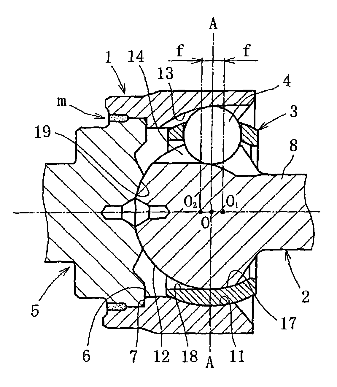
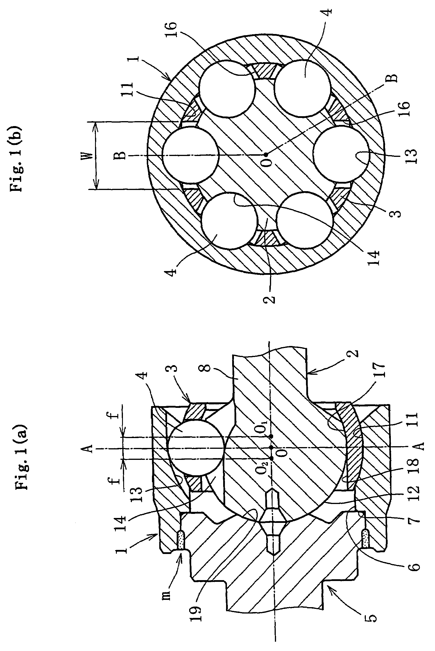
[0041]FIG. 1(a) and (b) show an embodiment of the invention, illustrating a fixed type constant velocity joint of the UJ type, (a) being a sectional view taken along the line B-O-B in (b), which is a sectional view taken along the line A-O-A in (a) The fixed type constant velocity joint in this embodiment comprises a joint outer ring 1, a joint inner ring 2, a cage 3, and torque transmitting balls 4 (hereinafter referred to simply as balls), and a stem shaft 5.

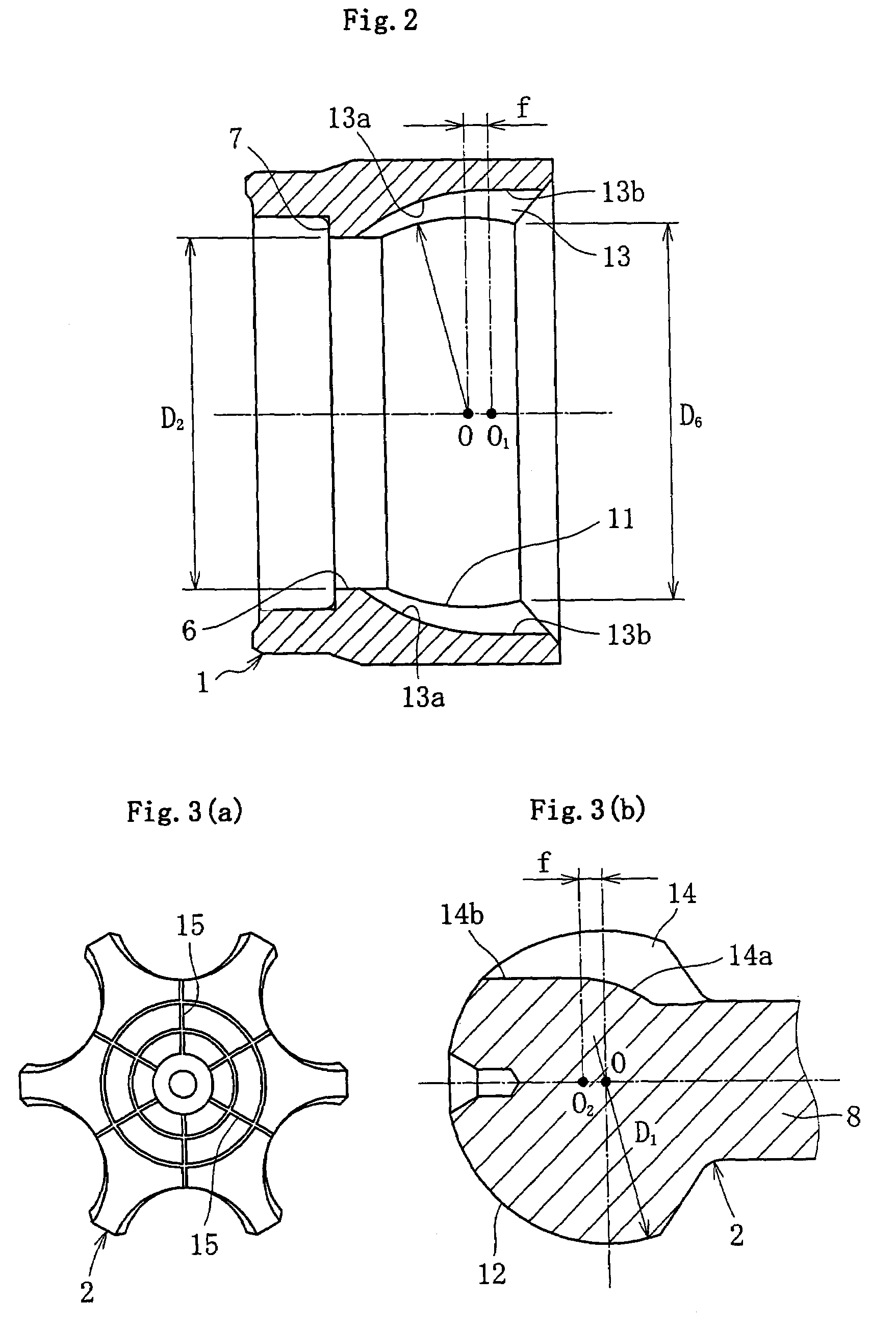
[0042]The joint outer ring 1, as shown in FIG. 2, is in the form of a sleeve that opens at one end for joining the stem shaft 5 and opens at the other end to receive the joint inner ring 2, cage 3 and balls 4. One end side (stem side) of the joint outer ring 1 is formed with an inner cylindrical surface 6 having a minimum inner diameter D2 larger than the outer diameter D1 of the joint inner ring 2 to allow passage of the joint inner ring 2 during assembling to be later described. The axial end of the inner cylindrical surface...


PUM


Abstract

A fixed type constant velocity joint includes a cylindrical joint outer ring having an inner spherical surface formed with circumferentially equispaced axially extending track grooves, a joint inner ring having an outer spherical surface formed with circumferentially equispaced axially extending track grooves, balls disposed in ball tracks defined by cooperation between the track grooves in the joint outer and inner rings, and a cage for holding the balls in the ball tracks. The rear open end of the joint outer ring has an inner diameter larger than the outer diameter of the joint inner ring, an inner diameter surface of said cage is a surface having a shape such that the region located forwardly of the axial center is capable of controlling the forward movement of the joint inner ring while the region located rearwardly of the axial center is capable of allowing the axial movement of the joint inner ring.

Description

BACKGROUND OF THE INVENTION[0001]1. Field of the Invention[0002]The invention relates to a fixed type constant velocity joint used in power transmission systems for automobiles and various industrial machines, for example, and adapted to only allow working angle displacement between two shafts on the driving and driven sides.[0003]2. Brief Description of the Prior Art[0004]The fixed type constant velocity joint is available, for example, in the UJ (undercut free) type. This fixed type constant velocity joint has a construction comprising a joint outer ring having an inner spherical surface formed with a plurality of circumferentially equispaced axially extending track grooves, a joint inner ring having an outer spherical surface formed with circumferentially equispaced axially extending track grooves paired with the track grooves in the joint outer ring, a plurality of balls disposed in ball tracks defined by cooperation between the track grooves in the joint outer and inner rings, ...

Claims


Application Information

Patent Timeline
Patent Type & Authority Patents(United States)
IPC IPC(8): F16D3/223F16D3/20F16D3/2237F16D3/2245
CPCF16D3/2233F16D3/2237F16D3/2245F16D2003/22303F16D2003/22313F16D2003/2232Y10S464/906F16D3/20
Inventor SONE, KEISUKENAKAKOJI, MASAFUMI
Owner NTN CORP
Why Eureka
Try Eureka