Method and apparatus for mechanically reconstructing ligaments in a knee prosthesis

a knee joint and ligament technology, applied in the field of knee joint prosthesis, can solve the problems of increased contact stress between the femoral component and the bearing member, dislocation sometimes exhibiting drawbacks of fixed bearing knees, so as to achieve the effect of substantially reducing or eliminating the disadvantages of the currently available knee joint prosthesis

Inactive Publication Date: 2006-12-26
BIOMET MFG CORP
View PDF17 Cites 245 Cited by
  • Summary
  • Abstract
  • Description
  • Claims
  • Application Information

AI Technical Summary

Benefits of technology

[0009]In one preferred embodiment, a knee joint prosthesis for replacing the articulating knee portion of a femur and a tibia includes a femoral component, a tibial component, a bearing member, a guide post and a linkage mechanism. The femoral component includes a first femoral bearing surface and a second femoral bearing surface. The tibial component includes a tibial bearing surface. The bearing member includes a first bearing surface which is operable to articulate with the first femoral bearing surface, a second bearing surface which is operable to articulate with the second femoral bearing surface and a third bearing surface which is

Problems solved by technology

However, fixed bearing knees sometimes exhibit drawbacks.
First, increased contact stresses may be created between the femoral component and the bearing member.
Second, fixed bearing knees may become dislocated if th

Method used


Image

  • Method and apparatus for mechanically reconstructing ligaments in a knee prosthesis
  • Method and apparatus for mechanically reconstructing ligaments in a knee prosthesis
  • Method and apparatus for mechanically reconstructing ligaments in a knee prosthesis

Examples


first embodiment

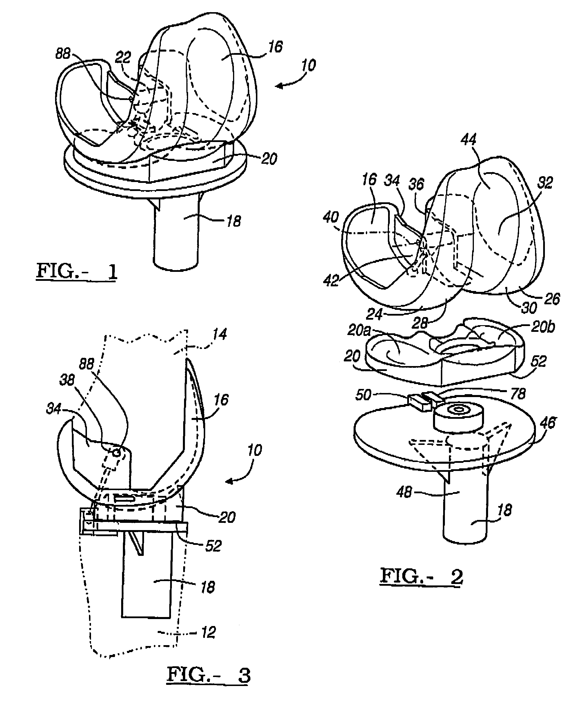
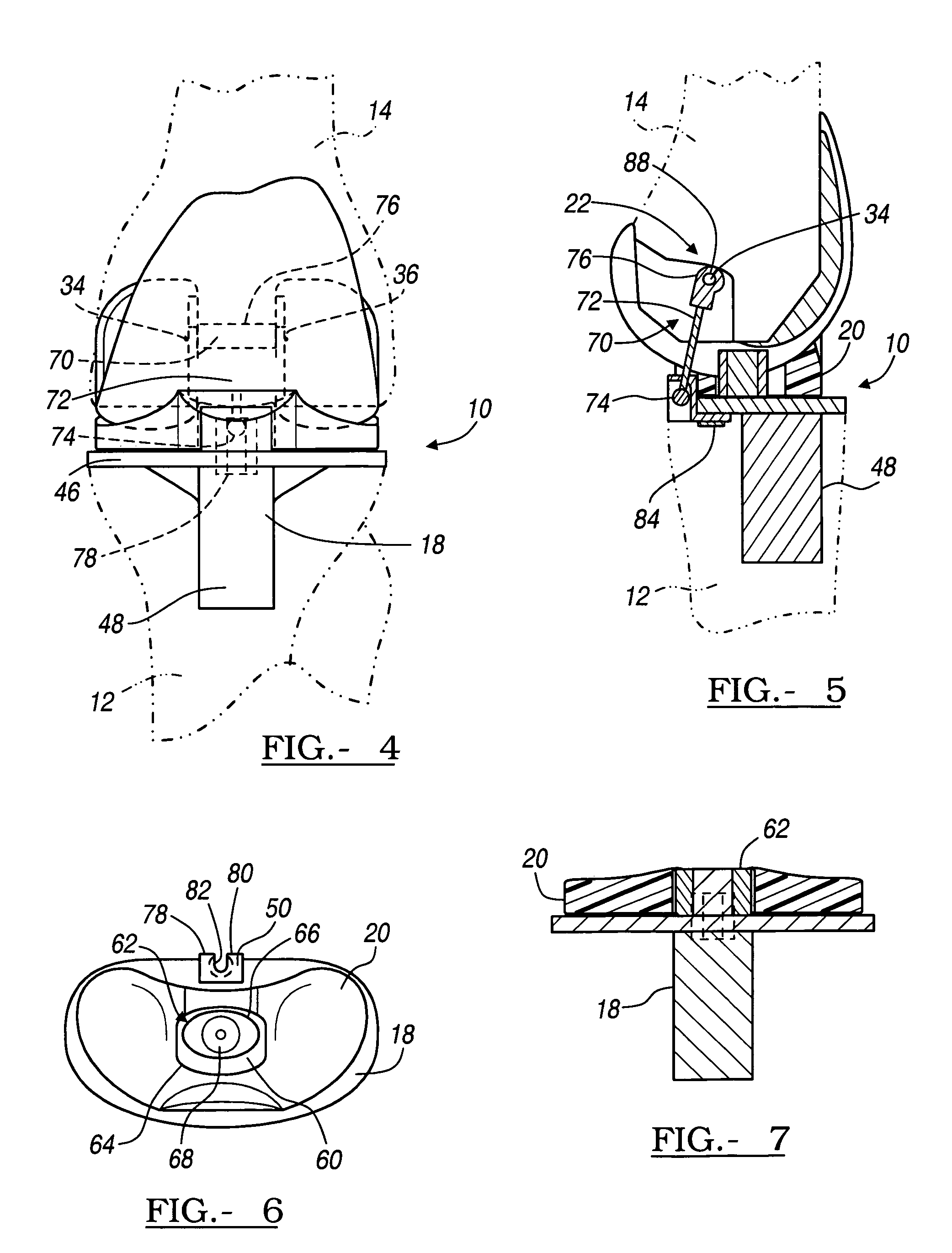
[0026]Referring to FIGS. 1–8e, a knee joint prosthesis 10 is shown in accordance with the teachings of the present invention. The knee joint prosthesis 10 is generally designed to be used when the posterior cruciate ligament (PCL) is resected. However, it is appreciated that the present invention may be utilized in knee replacements where other ligaments such as the anterior cruciate ligament (ACL) or other soft tissues that support the knee joint are resected. The knee joint 10 is shown in FIGS. 3–5 as being secured to the tibia 12 and the femur 14 of a surgically resected left knee joint, with the tibia 12 and the femur 14 shown in phantom, and with the understanding that a suitable right knee may be similarly constructed. The knee joint prosthesis 10 includes a femoral component 16, a tibial component 18, a floating bearing 20 and a linkage mechanism 22 coupling the femoral component 16 to the tibial component 18 and acting as the PCL replacement.

[0027]The femoral component 16 is...

second embodiment

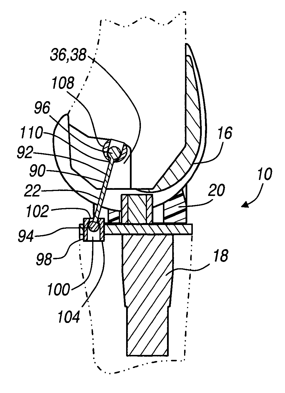
[0043]As shown in FIGS. 11–12, a linkage mechanism 90 for the prosthetic knee joint 10 having the floating bearing 20 is shown comprised of a bar 92 coupled to the femoral component 16 and to the tibial component 18. The bar 92 includes a first ball 94 attached to a first end and a second ball 96 attached to the second end. The bar 92 is shown to be formed of a rigid biocompatible metal such as cobalt-chromium-molybdenum alloy having suitable mechanical properties. However, it is contemplated that the bar 92 may be formed of various materials having varying mechanical properties or combinations of materials to optimize the performance of the knee joint prosthesis 10. For example, the bar 92 may be rigid, flexible, resilient and made from materials such as nylon, surgical steel or UHMWPE to provide the desired characteristics.

[0044]The first ball 94 end of the bar 92 is coupled to the tibial component 18 by a captured bore 98 that permits rotation and translation of the linkage mecha...


PUM


Abstract

The invention relates to a knee joint prosthesis for replacing the articulating knee portion of a femur and a tibia. The knee joint prosthesis includes a femoral component, a tibial component, a bearing member, a guide post and a mechanically reconstructed ligament. The femoral component includes a first femoral bearing surface and a second femoral bearing surface. The tibial component includes a tibial bearing surface. The bearing member includes a first bearing surface which is operable to articulate with the first femoral bearing surface, a second bearing surface which is operable to articulate with the second femoral bearing surface and a third bearing surface which is operable to articulate with the tibial bearing surface. The guide post extends from the tibial component. The mechanically reconstructed ligament is coupled to both the tibial component and the femoral component to prevent the knee joints from dislocating and guiding the femoral component along a desired path during extension and flexion.

Description

FIELD OF THE INVENTION[0001]This invention relates generally to a knee joint prosthesis which replaces the articulating knee portion of the femur and tibia, and more particularly, to a knee joint prosthesis having a mechanically reconstructed ligament.BACKGROUND OF THE INVENTION[0002]A knee joint prosthesis typically comprises a femoral component and a tibial component. The femoral component and the tibial component are designed to be surgically attached to the distal end of the femur and the proximal end of the tibia, respectively. The femoral component is further designed to cooperate with the tibial component in simulating the articulating motion of an anatomical knee joint.[0003]Motion of a natural knee is kinematically complex. During a relatively broad range of flexion and extension, the articular or bearing surfaces of a natural knee experience axial rotation, adduction and abduction, translation in the sagittal plane (rollback and sliding), and translation in the coronal pla...

Claims


Application Information

Patent Timeline
IPC IPC(8): A61F2/38A61F2/08
CPCA61F2/08A61F2/3868A61F2/3836A61F2310/00029
Inventor METZGER, ROBERT
Owner BIOMET MFG CORP
Why Eureka
Try Eureka