Ballast control IC with multi-function feedback sense

a multi-function feedback and ballast technology, applied in the field of electronic ballast control, can solve problems such as end-of-life detection problems and challenges in providing electronic ballasts, and achieve the effect of preventing component damag

Active Publication Date: 2006-12-26
INFINEON TECH AMERICAS CORP
View PDF10 Cites 34 Cited by
  • Summary
  • Abstract
  • Description
  • Claims
  • Application Information

AI Technical Summary

Benefits of technology

[0015]In accordance with the present invention, there is provided a multi-function feedback circuit that is incorporated into an electronic ballast control that can detect end of life (EOL) conditions and other faults. An AC EOL, a DC EOL, an open upper filament, an open lower filament, a broken upper cathode, a broken lower cathode and lamp removal can all be detected and the electronic ballast placed in a default mode to prevent component damage. The present invention also provides for an auto restart feature to ignite an exchanged lamp without having to cycle power. Th

Problems solved by technology

A design challenge in providing electronic ballasts is presented by the “end-of-

Method used


Image

  • Ballast control IC with multi-function feedback sense
  • Ballast control IC with multi-function feedback sense
  • Ballast control IC with multi-function feedback sense

Examples


Embodiment Construction

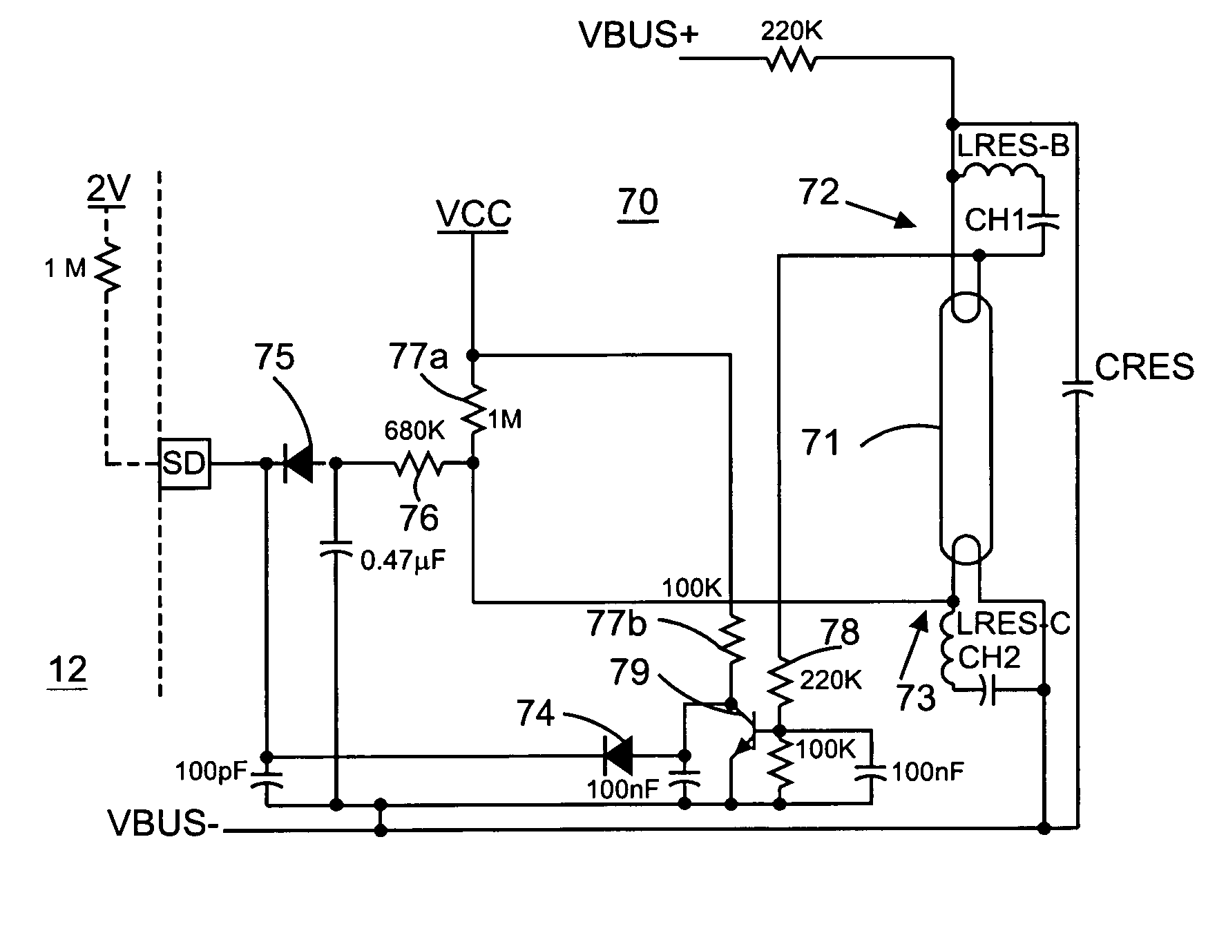
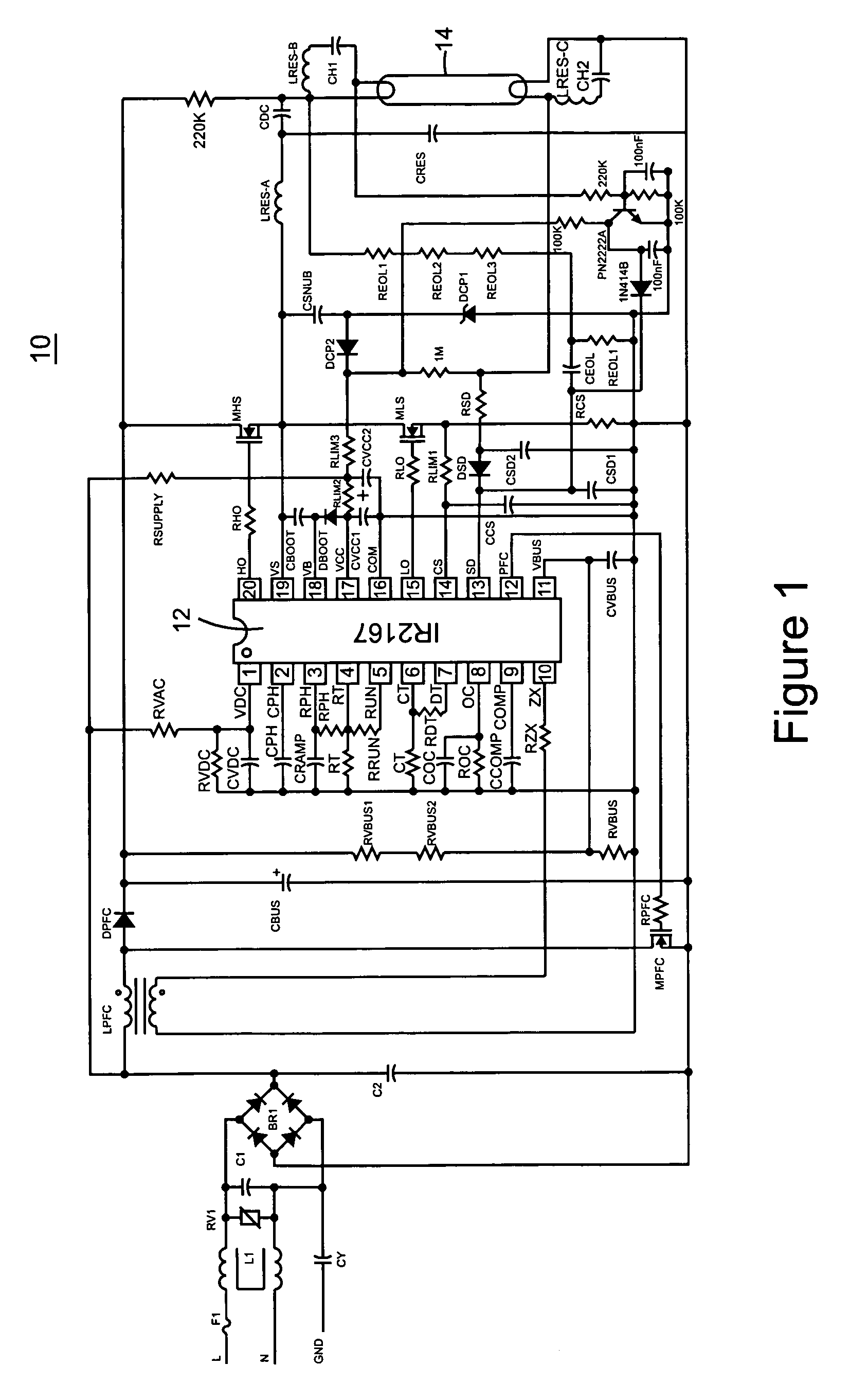
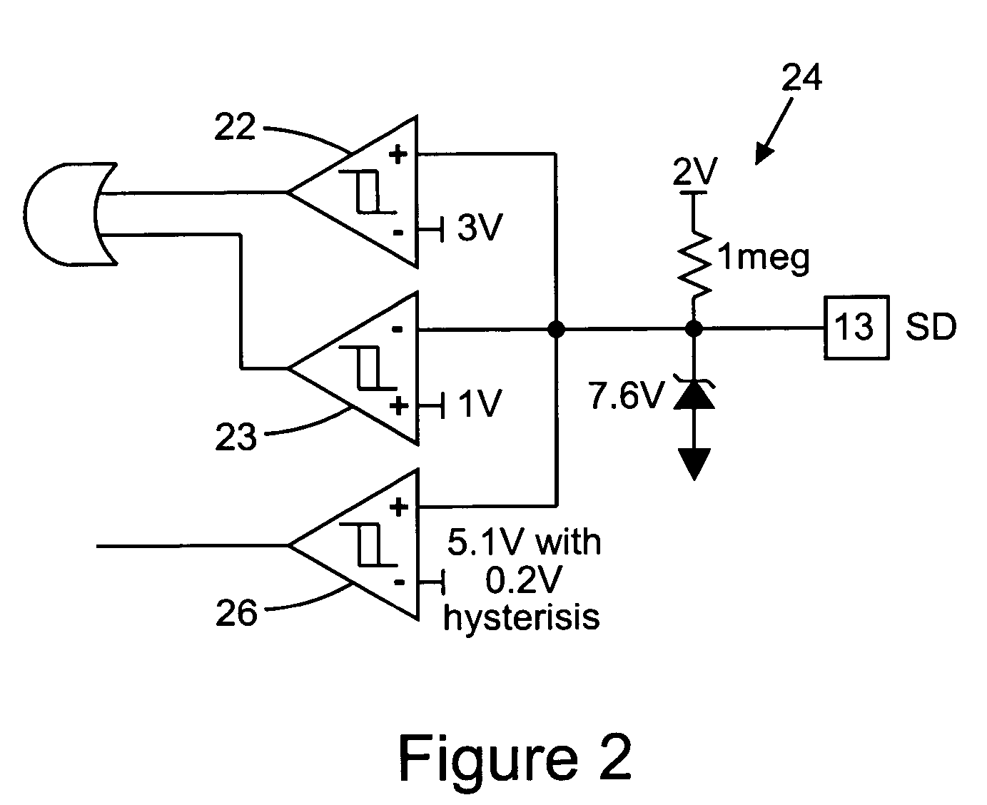
[0026]Referring now to FIG. 1, a circuit diagram for an electronic ballast is illustrated as circuit 10. Circuit 10 includes an electronic ballast control IC 12 that provides all the operational signals for controlling the electronic ballast. Preferably, control IC 12 provides drive signals to a high and low side switch MHS, MLS, respectively in a switching half bridge to direct power to lamp 14. Circuit connections in circuit 10 shown in dark lines represent high current, high frequency paths. The high frequency, high current paths should be minized in length to avoid or reduce high frequency noise events. Although control IC 12 does not handle high frequency, high current signals, it can easily be seen that control IC 12 controls power switches MHS, MLS and MPFC to direct power in the electronic ballast to operate lamp 14. Control IC 12 also receives feedback from lamp 14 provided on pin SD to measure performance characteristics of lamp 14. Control IC 12 also includes a switching ...


PUM


Abstract

A multi-function feedback sense input in an electronic ballast control indicates a number of lamp faults on the basis of lamp parameters exceeding specified thresholds. An end of life detection is achieved by conditioning a lamp feedback with a DC offset to provide a simple threshold comparison to determine if the lamp exceeds specified operational boundaries. An open filament, absent lamp or broken cathode is detected on the same feedback sense by detecting an open circuit in the lamp filament and driving the sense feedback to a shutdown state in the event of a filament open circuit. The ballast control includes a current sense feedback for detecting overcurrent conditions as well as lamp faults so that the control detects an end of life condition, lamp absence, broken lamp, open filament, broken cathode, overcurrent, hardswitching or failure to ignite fault with a minimum number of feedback sensors. The ballast control provides a number of protections with a simplified circuit to reduce cost and improve functionality of the electronic ballast control.

Description

RELATED APPLICATION[0001]This application is based on and claims benefit of U.S. Provisional Application No. 60 / 482,334, filed Jun. 24, 2003, entitled Ballast Control IC With Multi-function SD Pin, to which a claim of priority is hereby made.BACKGROUND OF THE INVENTION[0002]1. Field of the Invention[0003]The present invention relates generally to electronic ballast controls for gas discharge lamps, and relates more particularly to an electronic ballast control with circuitry to obtain multi-function feedback sense features.[0004]2. Description of Related Art[0005]Electronic ballasts for controlling fluorescent lamps typically use electronics for preheating the lamp filaments, striking or igniting the lamp, driving the lamp to a given power, detecting lamp fault conditions, and safely deactivating the circuit.[0006]Electronic ballasts for gas discharge circuits have come into widespread use because of the availability of power MOSFET switching devices and insulated gate bipolar trans...

Claims


Application Information

Patent Timeline
IPC IPC(8): H05B37/02H05B41/298
CPCH05B41/2981H05B41/2985
Inventor CONTENTI, CECILIAGREEN, PETERRIBARICH, THOMAS J.
Owner INFINEON TECH AMERICAS CORP
Why Eureka
Try Eureka