Optical device

a technology of optical devices and boroscopes, which is applied in the field of endoscopes, microscopes and boroscopes, can solve the problems of eye irritation, loss of as much as 50% of the light received from objects, and loss of as much as 50% of the remaining information

Inactive Publication Date: 2006-12-26
VISIONSENSE LTD
View PDF45 Cites 61 Cited by
  • Summary
  • Abstract
  • Description
  • Claims
  • Application Information

AI Technical Summary

Benefits of technology

The present invention provides a new way to make 3D images using a special lens and sensor technology. The invention solves problems with previous methods.

Problems solved by technology

The technical problem addressed in this patent text is the need for a stereoscopic image detection device that can provide a high-quality image with small cross-section and high image quality, while also being flexible and efficient in terms of optical and mechanical constraints. The conventional methods require a wider optical path and have limitations in terms of resolution and color imaging. The invention proposes a solution by advancing the image pick-up device to the frontal part of the endoscope and utilizing a monochromatic detector and a multi-wavelength-illuminating device to achieve color stereo imagery with one sensor.

Method used


Image

  • Optical device
  • Optical device
  • Optical device

Examples


Embodiment Construction

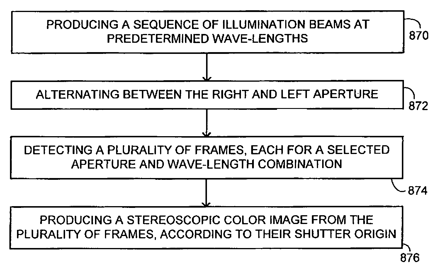
[0073]The present invention overcomes the disadvantages of the prior art by providing a continuous vision stereoscopic apparatus, using a generally lenticular lens layer, a light sensor array and an image processing system.

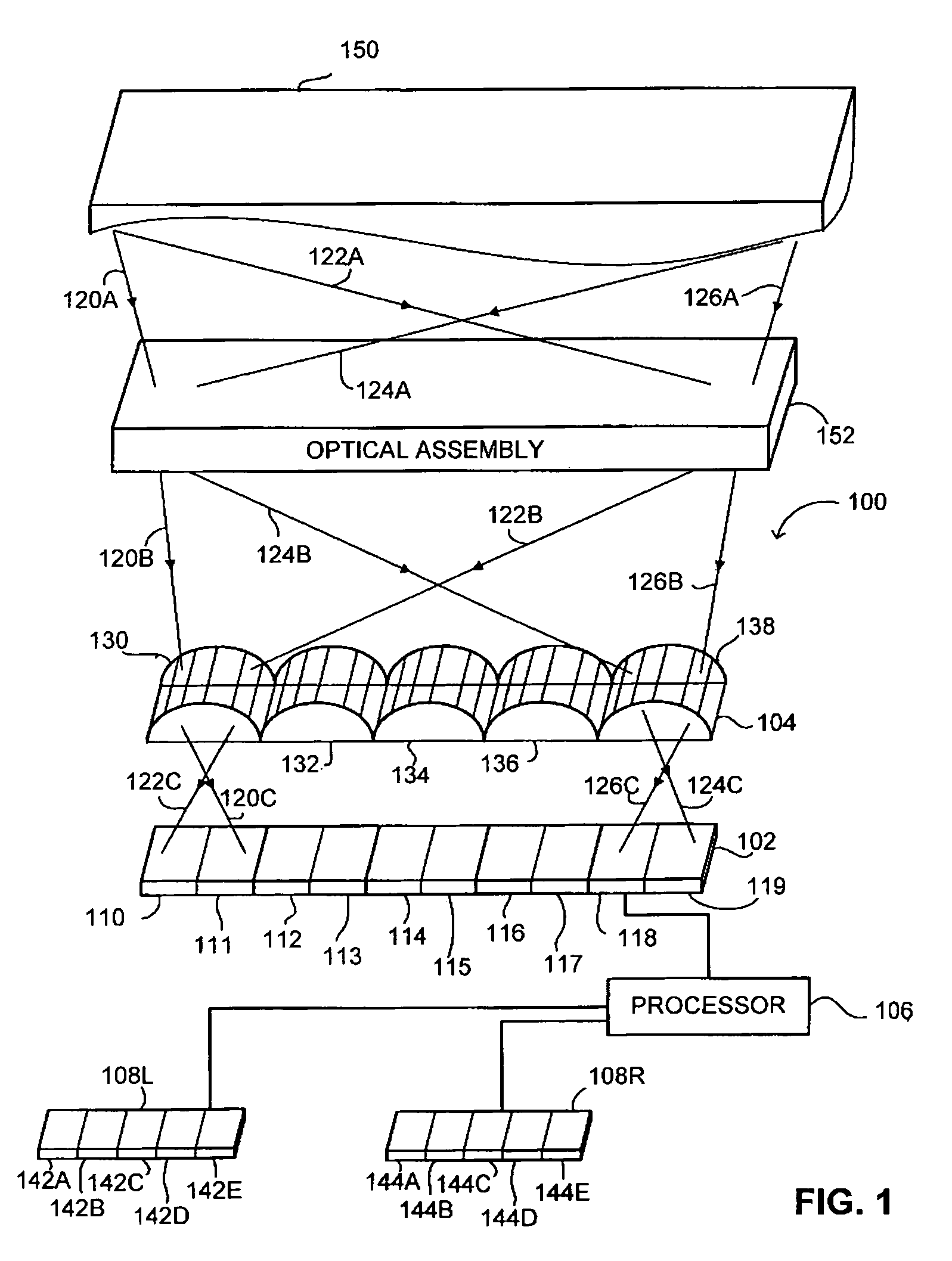
[0074]Reference is now made to FIG. 1, which is a schematic illustration of a three dimensional object and a stereoscopic vision apparatus, generally referenced 100 constructed and operative in accordance with a preferred embodiment of the present invention. Apparatus 100 includes a lenticular lens layer 104, a light sensor array 102, a processor 106 and two display devices 108R and 108L. Apparatus 100 is placed in front of a three-dimensional object 150. An optical assembly 152 is placed between apparatus 100 and object 150, for focusing the image of object 150 on light sensor array 102.

[0075]Light sensor array 102 includes a plurality of sensors 110, 111, 112, 113, 114, 115, 116, 117, 118 and 119. Lenticular lens layer 104 includes a plurality of lenticular elem...


PUM


Abstract

Stereoscopic device including at least two apertures, each including a light valve, a multi wavelength light sensor array and a controllable multi wavelength illumination unit, producing at least two alternating beams of light, each of the beams of light is characterized as being in a different range of wavelengths, wherein each light valve is operative to open at a different predetermined timing and wherein the multi wavelength light sensor array detects a plurality of images, each of the images corresponding to a predetermined combination of an open state of a selected one of the light valves and a selected one of the modes.

Description


Claims


Application Information

Patent Timeline
Owner VISIONSENSE LTD
Why Eureka
Try Eureka