
Communication system

a communication system and communication technology, applied in the field of communication systems, can solve the problems of reducing communication speed, inability to accurately obtain a reception signal from a transmission signal, etc., and achieve the effect of improving the character of the trailing edge of a reception signal and high speed

Inactive Publication Date: 2006-12-26
HONDA MOTOR CO LTD
View PDF23 Cites 1 Cited by
  • Summary
  • Abstract
  • Description
  • Claims
  • Application Information

AI Technical Summary

Benefits of technology

[0015]It is therefore an object of the invention to provide a communication system and a reception circuit therefor which can accurately obtain a reception signal from a signal transmitted over two-wire type transmission lines without significantly decreasing the communication speed.
[0017]In such a communication system according to the invention, since each of the nodes incorporates terminating resistors associated with the two-wire type transmission lines, no increase in the time constant occurs in the transmission lines when viewed from a node even when there is a break of one of the transmission lines or poor contact between the node and the transmission line, which makes it possible to accurately obtain a reception signal from a signal transmitted over the two-wire type transmission lines without any reduction in the communication speed.
[0019]In such a communication system according to the invention, the characteristics of a trailing edge of a reception signal can be improved even in the case of reception of a transmission signal having a transient waveform under the influence of a large time constant, which allows communication at a high speed.
[0021]With a reception circuit having such a configuration, the characteristics of the trailing edge of a reception signal can be improved even in the case of reception of a transmission signal having a transient waveform under the influence of a large time constant, which makes it possible to configure a reception circuit capable of communication at a high speed.

Problems solved by technology

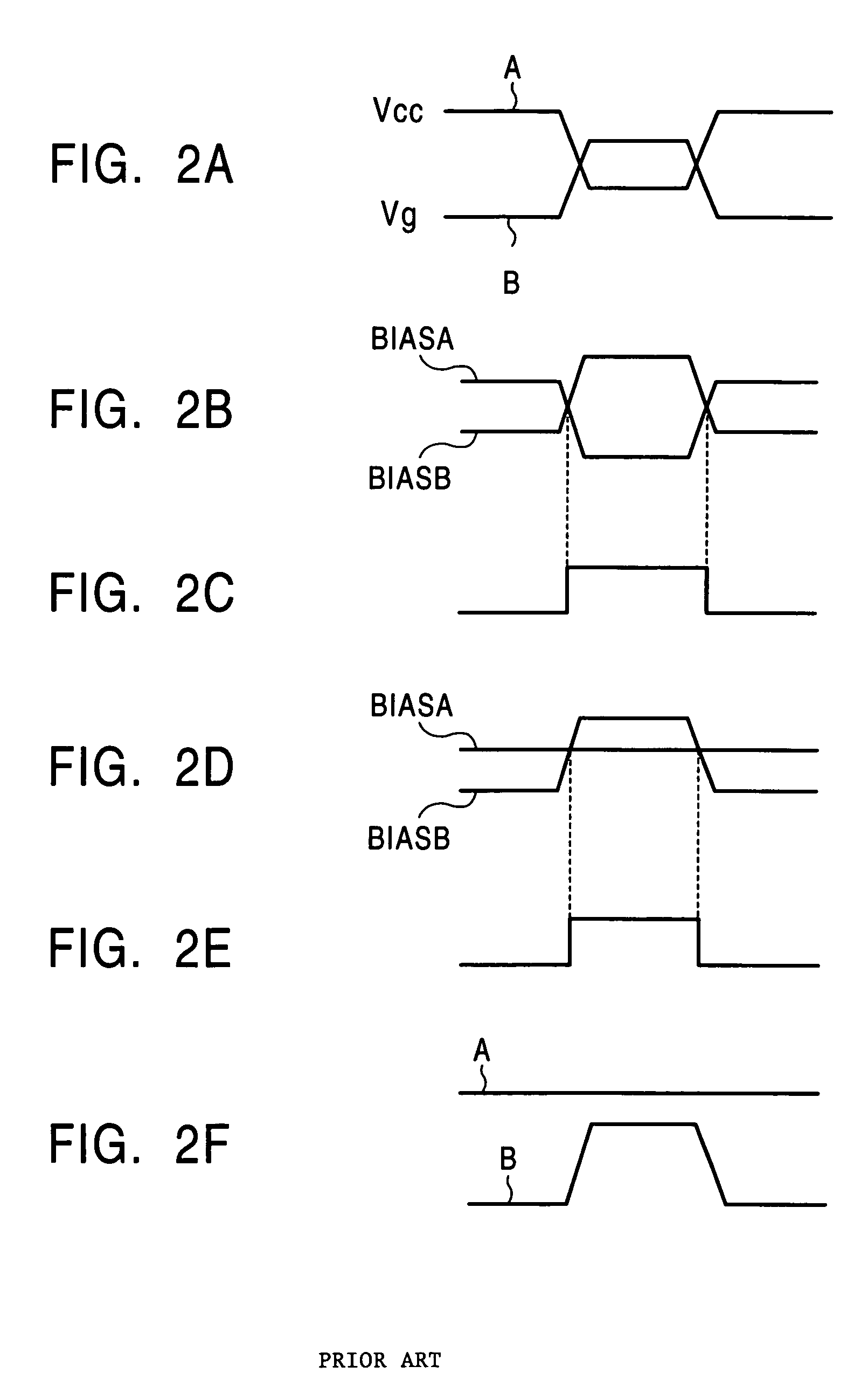
A problem has arisen in a transmission / reception circuit in that it is impossible to accurately obtain a reception signal from a transmission signal having a transient waveform under such influence of a large time constant without decreasing the communication speed.

Method used


Image

  • Communication system
  • Communication system
  • Communication system

Examples


Embodiment Construction

[0033]An embodiment of the invention will now be described in detail with reference to the drawings.

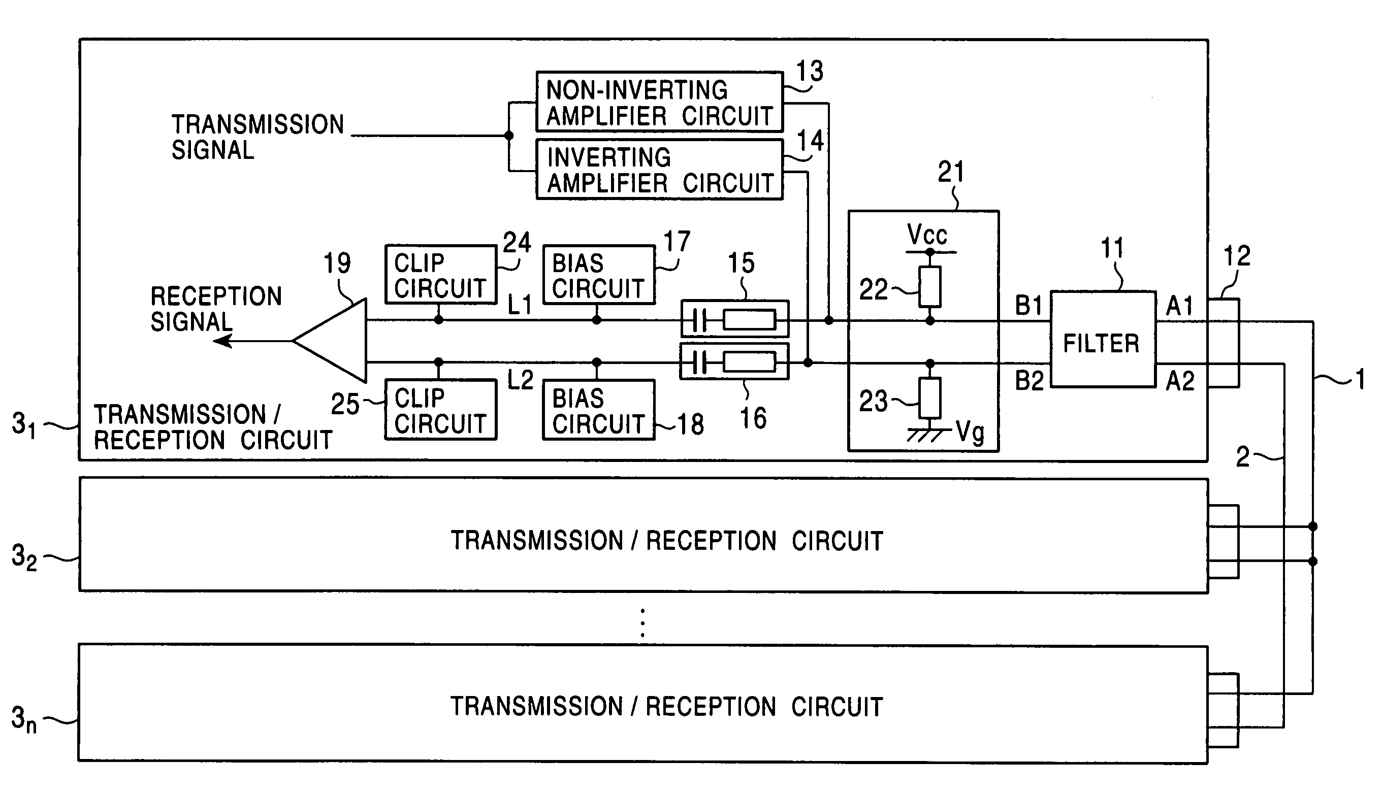
[0034]FIG. 7 shows a communication system according to the invention in which parts identical to those in the conventional communication system shown in FIG. 1 are indicated by like reference numbers. No terminating resistor is directly connected to two-wire type transmission lines 1 and 2. In a transmission / reception circuit 31, an inverting amplifier circuit 14 and an AC coupling circuit 15 are connected to a connection terminal B1 of a filter 11 located opposite to terminals A1 and A2 connected to the transmission lines 1 and 2, and a non-inverting amplifier circuit 13 and an AC coupling circuit 16 are connected to a connection terminal B2, which has a configuration similar to that of a conventional system. In the communication system according to the invention, however, a distributed termination circuit 21 is further connected to the connection terminals B1 and B2. The distributed...


PUM


Abstract

A communication system in which a reception signal can be accurately obtained from a signal transmitted over two-wire type transmission lines without any significant reduction in the communication speed. The communication system utilizing two-wire type transmission lines for transmitting transmission signals in opposite phases has a plurality of nodes connected to the two-wire type transmission lines, and each of the nodes incorporates terminating resistors acting upon the two-wire type transmission lines. A node which includes a reception circuit for receiving a transmission signal has an AC coupling circuit for extracting AC components in a transmission signal input through the transmission lines, a bias circuit for applying a bias voltage to a signal output from the AC coupling circuit and a clip circuit for clipping the level of a signal output from the bias circuit, which are provided at each of the two-wire type transmission lines.

Description

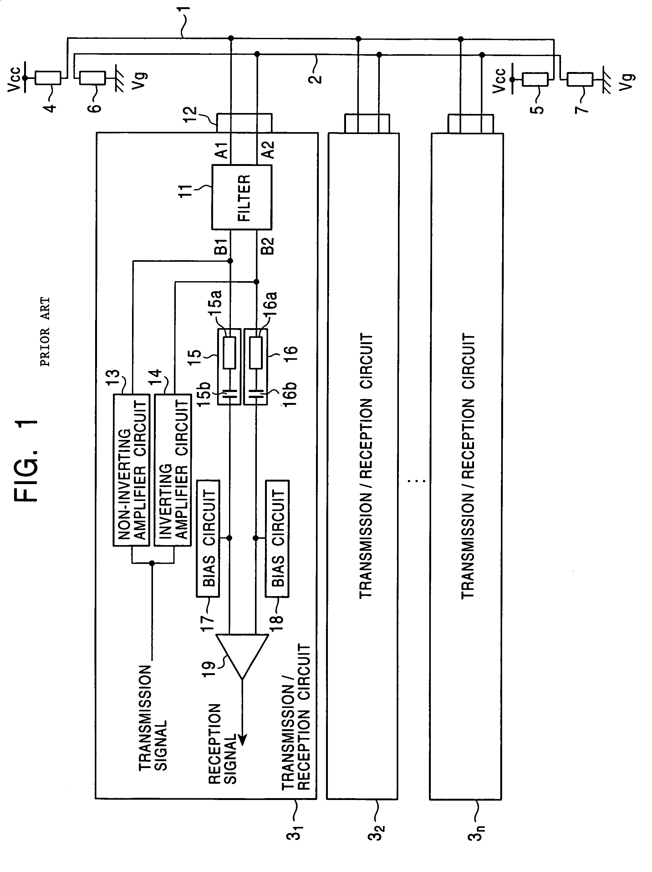
BACKGROUND OF THE INVENTION[0001]1. Field of the Invention[0002]The present invention relates to a communication system having a plurality of nodes connected to a common transmission line.[0003]2. Description of the Related Art[0004]In a conventional communication system, as shown in FIG. 1, a plurality of nodes, i.e., transmission / reception circuits 31 through 3n are connected to two-wire type transmission lines 1 and 2. All of the transmission / reception circuits 31 through 3n have the same configuration. A positive potential Vcc (e.g., 5 V) is supplied to one end of the transmission line 1 through a terminating resistor 4, and the positive potential Vcc is similarly supplied to the other end of the transmission line 1 through a terminating resistor 5. A ground potential Vg (e.g., 0 V) is supplied to one end of the transmission line 2 through a terminating resistor 6, and the ground potential Vg is similarly supplied to the other end of the transmission line 2 through a terminating...

Claims


Application Information

Patent Timeline
Patent Type & Authority Patents(United States)
IPC IPC(8): H04B3/00H04L25/00
CPCH04L25/0292H04L25/0298H04L25/0272
Inventor NAGATANI, YUJIIWAMOTO, KAZUYAHASHIMOTO, HIROSHI
Owner HONDA MOTOR CO LTD
Learn More