Spreading code synchronization method, receiver, and mobile station

a synchronization method and code technology, applied in the direction of synchronising arrangement, digital transmission, electrical equipment, etc., to achieve the effect of reducing the time necessary for identification

Active Publication Date: 2006-12-26
NTT DOCOMO INC
View PDF5 Cites 23 Cited by
  • Summary
  • Abstract
  • Description
  • Claims
  • Application Information

AI Technical Summary

Benefits of technology

[0019]Further, the spreading code synchronization method according to the present invention may comprise a third step carried out between the first and second steps. This third step is a step of detecting a second spreading code group, using as candidates only groups including the arbitrary number of second spreading codes informed by the first base station (second spreading codes assigned to respective base stations located around the first base station). In this case, the second step is preferably configured to perform the synchronous detection, using as candidates only the arbitrary number of second spreading codes informed by the first base station, out of the second spreading codes included in the second spreading code group detected in the third step. The reason is that for detection of a scrambling code group to which the handover destination cell belongs, there is no need for determining correlations with all the group ID codes and it is sufficient to determine correlations with only the group ID codes to which the informed scrambling codes belong (normally, about 20 codes). On the occasion of identifying the scrambling code of the handover destination cell, there is no need for determining the correlations with all the scrambling codes prepared in the mobile communication system, but it is sufficient to determine the correlations with only the informed scrambling codes, which can largely decrease the time necessary for the identification.
[0020]After the first and second steps, or the first to third steps are repeated either for a predetermined time or a predetermined number of times, and when the received timing of the mask symbol from the second base station is not detected, it is preferable to perform detection of the received timing of the mask symbol from the second base station, using received timings of all the scrambling codes as candidates without exception. The reason is that, even if the received timing of the scrambling code mask from the connecting cell coincides with the received timing of the scrambling code mask of the handover destination cell, the received timing of the scrambling code mask of the handover destination cell can be detected and it thus becomes feasible to detect the cell of the handover destination.
[0021]A receiver according to the present invention comprises, as a configuration for implementing the above-stated spreading code synchronization method (the spreading code synchronization method according to the present invention), first means for detecting a received timing of a mask symbol from a second base station in a state in which a received timing of a mask symbol from a first base station is excepted from candidates of received timings for synchronous detection; and second means for performing the synchronous detection of a second spreading code assigned to the second base station. Particularly, the receiver constitutes part of communication means of the mobile station in the mobile communication system. Specifically, the receiver constitutes part of the communication means included in the mobile information devices such as the mobile telephones, computers, electronic notes, and so on, or part of the communication means provided in the automobiles, bicycles, motorcycles, trains, airplanes, ships, and so on. This structure permits the timing of the scrambling cod

Problems solved by technology

The conventional cell search methods, when applied as they were, had the problem that the received signa

Method used


Image

  • Spreading code synchronization method, receiver, and mobile station
  • Spreading code synchronization method, receiver, and mobile station
  • Spreading code synchronization method, receiver, and mobile station

Examples


first embodiment

[0056]FIG. 5 is a diagram to show a signal frame transmitted from the base station to the mobile station in the spreading code synchronization method according to the present invention. This signal frame includes a mask symbol C1 spread by only a common short code being a first spreading code common to base stations, and an information data symbol C2 spread by a combination of a scrambling code being a second spreading code assigned to each base station and the common short code being the first spread code common to the base stations, and the mask symbol C1 is inserted in every period of the scrambling code.

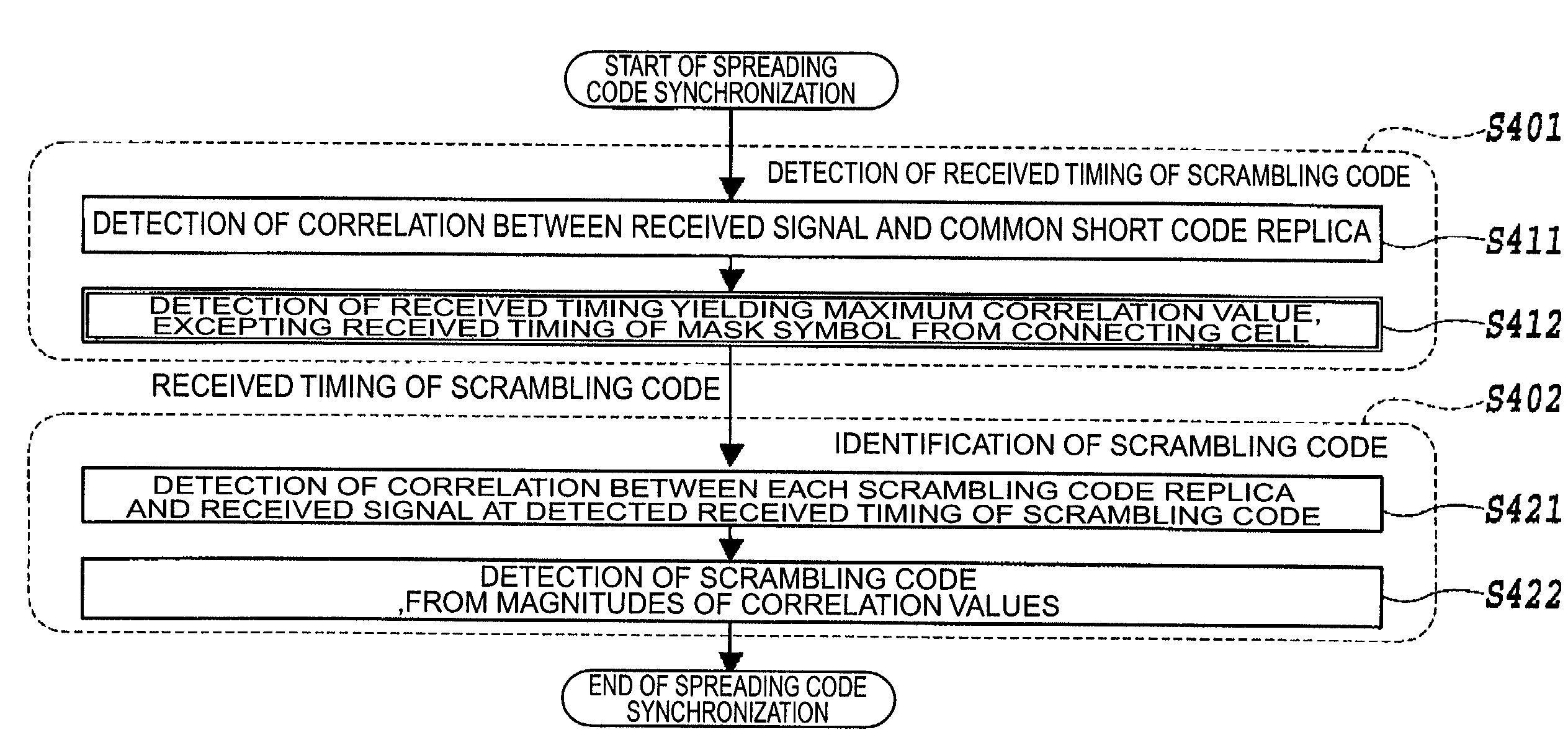
[0057]FIG. 6 is a flowchart for explaining the operation of the first embodiment of the spreading code synchronization method according to the present invention.

[0058]In the first embodiment the following processes are successively performed for the signal frame shown in FIG. 5: detection of received timing of the scrambling code (S401); and identification of the scrambling code....

second embodiment

[0067]The second embodiment permits the received timing of the scrambling code mask of the signal transmitted from the handover destination cell to be detected without detecting the received timing of the scrambling code mask from the connecting cell, which enables the detection of the cell of the handover destination.

[0068]Next FIG. 10 is a flowchart for explaining the operation of the third embodiment of the spreading code synchronization method according to the present invention. In the third embodiment, the following processes are carried out for the signal frame shown in FIG. 5: detection of received timing of scrambling code (S801); and identification of scrambling code (S802). First, the correlation is detected between the received signal and the common short code replica (S811) and the received timing of the scrambling code mask of the handover destination cell is detected based thereon (S812). At this time, in order to avoid reception of the signal transmitted from the conn...

fifth embodiment

[0079]In the fifth embodiment, there is no need for determining the correlations for all the scrambling codes prepared in the mobile communication system on the occasion of identifying the scrambling code of the handover destination cell, but it is sufficient to determine the correlations for only the informed scrambling codes (normally, about 20 codes), which can largely decrease the time necessary for the identification.

[0080]Next, FIG. 13 is a drawing to show a signal frame transmitted from the base station to the mobile station in the sixth embodiment of the spreading code synchronization method according to the present invention. This signal frame includes a mask symbol C1 spread by only the common short code, an information data symbol C2 spread by a combination of the common short code and the scrambling code, an information data symbol C3 spread by the scrambling code timing indication code, and an information data symbol C4 spread by a scrambling code group ID code. N mask ...


PUM


Abstract

The present invention relates to a spreading code synchronization method and others for implementing fast cell search during entry of a mobile station into a soft handover mode in an intercell asynchronous system. In the spreading code synchronization method according to the present invention, a correlation is first detected between a received signal and a common short code, and a received timing of a scrambling code mask of a handover destination cell is detected based thereon. At this time, in order to avoid reception of a signal transmitted from a connecting cell, a received timing of a mask symbol from the connecting cell is excepted from a search range for the received timing of the scrambling code mask of the handover destination cell. The spreading code synchronization method further includes steps of detecting for each of scrambling code candidates a correlation between the received signal and a code of a product of a scrambling code and a common short code at the received timing of the scrambling code mask of the handover destination cell detected, and identifying the scrambling code of the signal transmitted from the handover destination cell, from magnitudes of correlation values.

Description

BACKGROUND OF THE INVENTION[0001]1. Field of the Invention[0002]The present invention relates to a spreading code synchronization method and others in mobile communication systems employing the direct sequence code division multiple access scheme for multiple access through use of spectrum spreading.[0003]2. Related Background Art[0004]The direct sequence code division multiple access (DS-CDMA) scheme enables a plurality of users to perform communications in an identical frequency band by transmission based on secondary modulation to spread the conventional information data modulated signal by a fast rate spreading code. Each user is identified by identifying a spreading code assigned to every user. For this reason, the receiver side needs to restore the received input signal of wide band to the original signal of narrow band in a despreading process, prior to execution of the conventional demodulation process. In the despreading process on the receiver side, correlation detection i...

Claims


Application Information

Patent Timeline
IPC IPC(8): H04L7/00H04Q7/20H04B1/707H04B1/7083H04B7/26
CPCH04B1/70735H04B1/7083H04B1/7073H04W36/08
Inventor HANADA, YUKIKOHIGUCHI, KENICHISAWAHASHI, MAMORU
Owner NTT DOCOMO INC
Why Eureka
Try Eureka