System for creating microscopic digital montage images

a technology of microscopic digital and montage images, applied in the field can solve the problems of limited application of microscopic digital imaging, limited investigators looking at a single frame, and “sub-sampling” problems of all singles, and achieve high throughput montage, high-quality montage, and accurate focus control of optical elements

Inactive Publication Date: 2006-12-26
CARL ZEISS MICROSCOPY GMBH
View PDF84 Cites 88 Cited by
  • Summary
  • Abstract
  • Description
  • Claims
  • Application Information

AI Technical Summary

Benefits of technology

[0015]Accordingly, it is a benefit of the invention that it provides a microscopic imaging system for whole slide montage in which standard microscope optics, off the shelf cameras, a simple motorized stage, and a pulse light illumination system can be used to produce precisely aligned image tiles, and acquire these image tiles at a speed limited primarily by the camera frame rate.
[0016]The present invention uses a strobe light, triggered by a direct Ronchi ruler or other stage-positioning device, to produce precisely aligned image tiles that can be made into a montage image of tissue sections on a microscope slide. Significantly, due to the short light pulse emitted by a strobe, clear images can be obtained without stopping the microscope stage. This significantly increases the image throughput while decreasing the expense and precision required in the stage mechanics.
[0017]In one embodiment, a strobe arc is placed at the position of the lamp bulb in a standard microscope system. The camera shutter is opened and the strobe is fired in response to the position of the stage as reported by a direct position sensor. If stray light is minimized, the camera exposure can be much longer than the strobe flash, allowing low cost cameras to be utilized.
[0018]It is another benefit of the invention to significantly increase the image throughput of a tiling image system by allowing, through the use of the strobe light, continuous motion of the slide under the microscope. The inventive system thus eliminates the need to stop the microscope stage to capture an image.
[0019]It is another benefit of the invention to reduce the demands of camera, stage, and strobe synchronization by controlling the firing of the strobe light based on direct stage position feedback, thereby substantially reducing the mechanical precision required of the stage and camera components.
[0020]It is another benefit of the invention to use a pre-scan process applied to a macroscopic image of the entire slide, to guide a high-resolution slide scanning process and ensure high-quality images of the entire specimen are acquired. The pre-scan process includes an image cropping component, a tissue finding component, a scan control component, a focus point selection component, a focal surface determination component, and a scan component. The image cropping and tissue finding components identify interesting regions on the slide to be scanned. The focus point selection and focal surface determination components ensure that a high quality image is captured by the scanning process, by enabling accurate focus control to be maintained.

Problems solved by technology

Though numerous studies have shown that digital image quality is acceptable for most clinical and research use, some aspects of microscopic digital imaging are limited in application.
Perhaps the most important limitation to microscopic digital imaging is a “sub-sampling” problem encountered in all single frame images.
The field of view problem limits an investigator looking at a single frame because what lies outside the view of an image on a slide cannot be determined.
The resolution-based problem occurs when the investigator looking at an image is limited to viewing a single resolution of the image.
However, these systems do not lend themselves to significant collaborations, documentation or computer based analysis.
To be successful, remote transmission requires lossy video compression techniques to be used in order to meet the network bandwidth requirements, or requires significant delays in the image display if lossless transmission is used.
In addition, lossy compression on the order required for real-time remote transmission, severely limits computer-based analysis, as well as human diagnosis, due to the artifacts associated with lossy compression techniques.
The “virtual slide” option has some limitations, however.
One of the limitations is file size.
A much more difficult limitation with the prior systems is an image capture time problem.
Given today's technology, the rate of slide motion is a significant limiting factor largely because the existing imaging systems require the slide to come to a stop at the center of each field to capture a blur free image of the field.
Continuous light, however, is a significant limitation for digital imaging in that the slide, which must move to capture an entire image, but must be stationary with respect to the camera during CCD integration, thus moving the slide from the light.
Moreover, slide motion during integration results in a blurred image.
This pattern requires precise, expensive mechanics, and its speed is inherently limited by the inertia of the stage.
The three-dimensional characteristic of a typical tissue sample and the slide places additional limitations on the imaging system.

Method used


Image

  • System for creating microscopic digital montage images
  • System for creating microscopic digital montage images
  • System for creating microscopic digital montage images

Examples


Embodiment Construction

[0035]Reference will now be made in detail to the preferred embodiments of the present invention, examples of which are illustrated in the accompanying drawings. The following paragraphs describe the functionality of the inventive system and method for focus controlled, high throughput montage imaging of microscope slides using a standard microscope, camera, and a motorized mechanical stage.

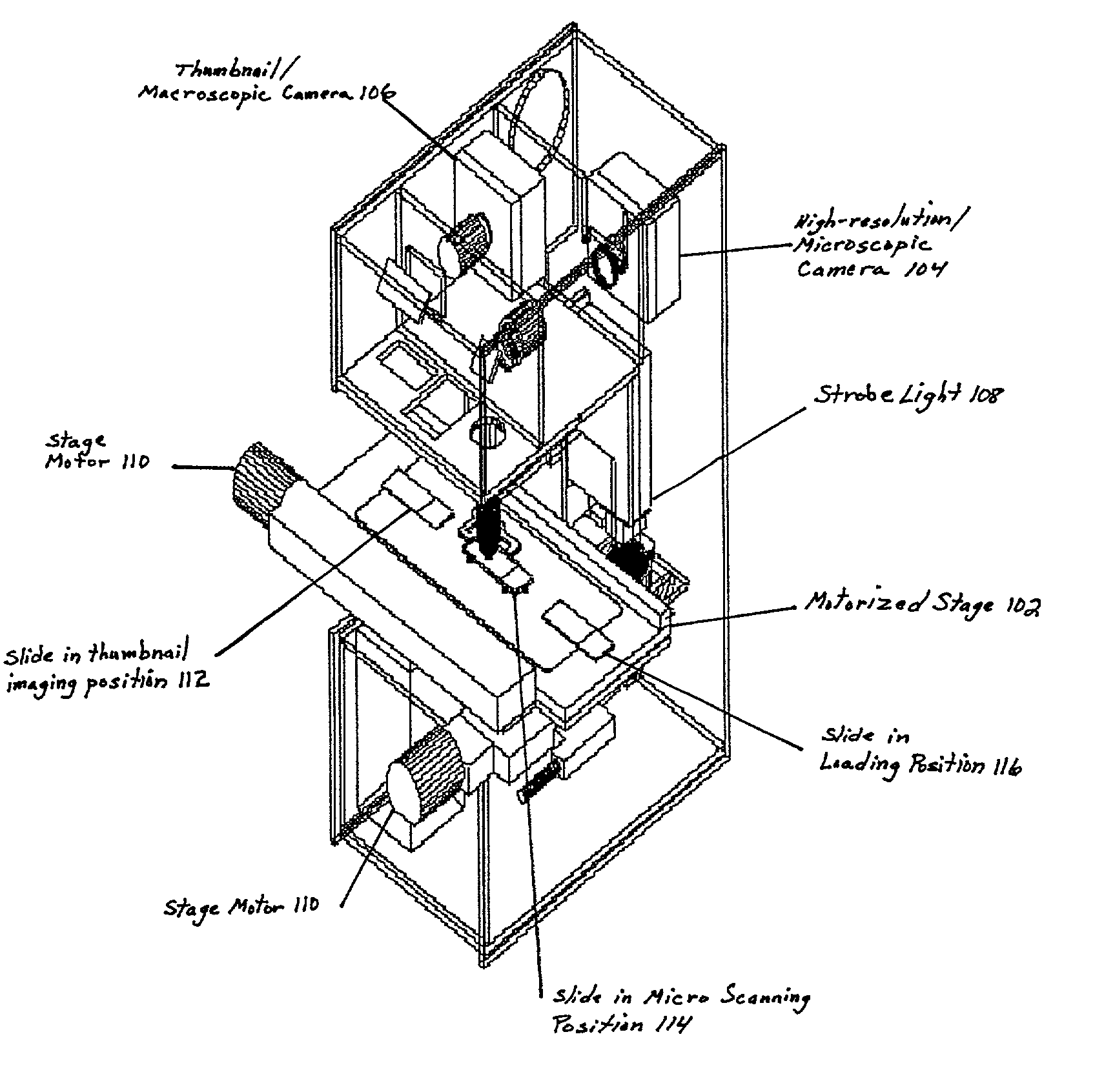
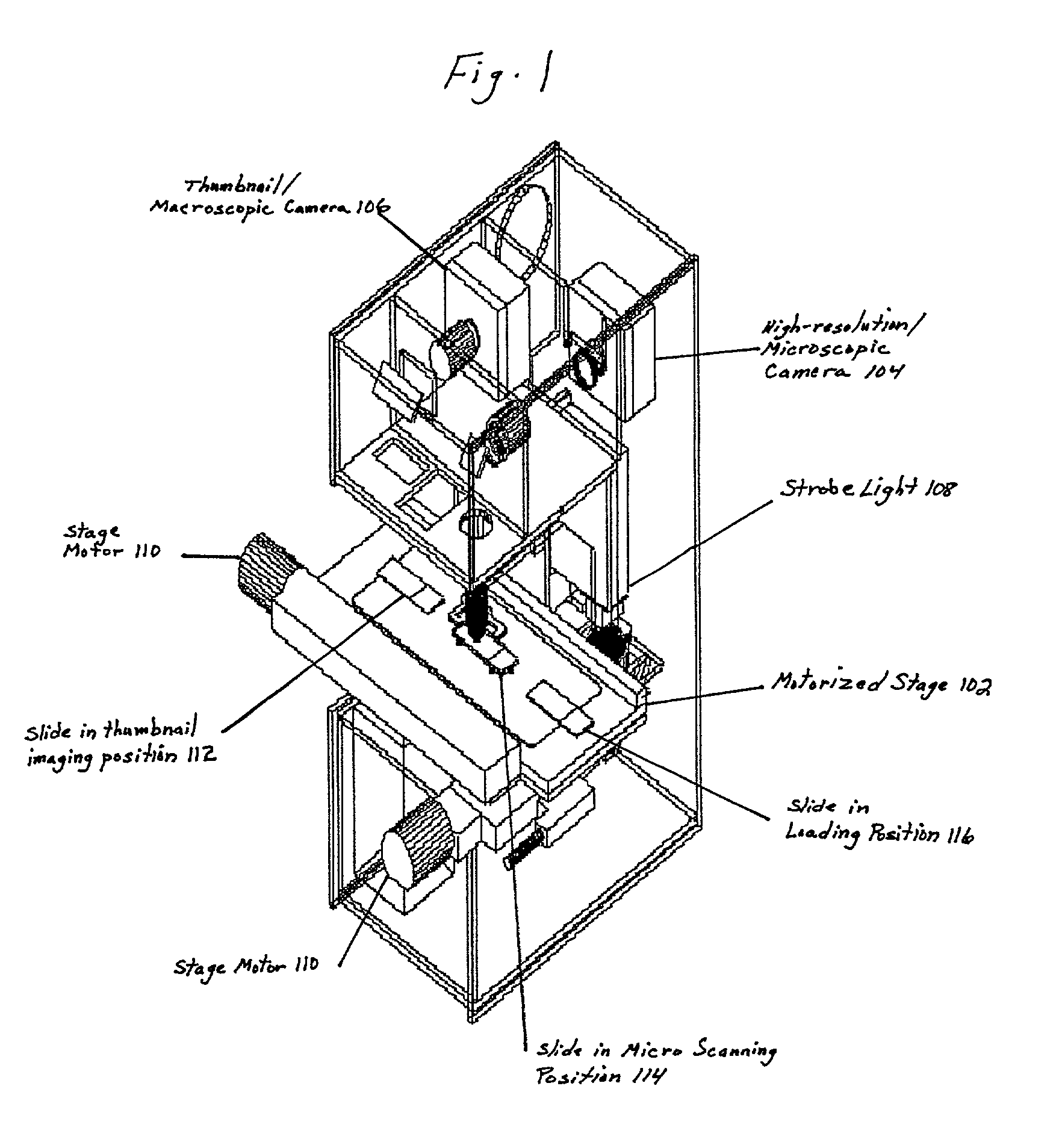
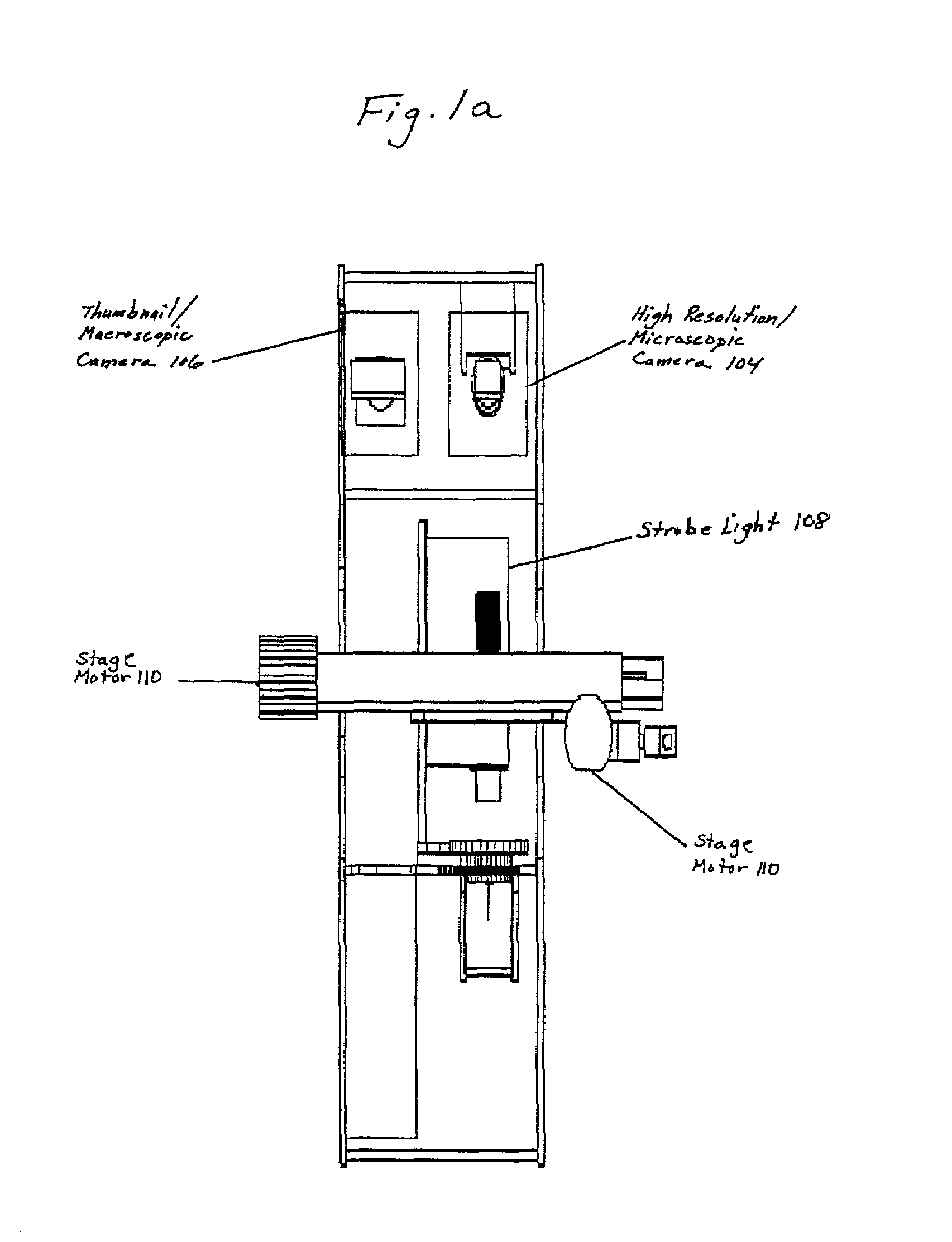
[0036]FIG. 1 illustrates a first embodiment of the imaging apparatus of the present invention. FIGS. 1a–1c illustrate front, side, and top views, respectively, of the imaging apparatus illustrated in FIG. 1. It should be noted that not all components that may be included in an imaging apparatus are illustrated in FIGS. 1–1c. For example, a stage support that attaches the stage to the imaging apparatus is not illustrated so as not to obstruct the view of other components. In this embodiment, a slide 112 to be imaged is placed on a thumbnail imaging position in a slide holder on a motorized stage 1...


PUM


Abstract

An imaging apparatus is disclosed. The imaging apparatus includes a motorized stage, a camera focussed relative to the stage, and a processor coupled to the camera. The processor contains instructions which, when executed by the processor, cause the processor to capture an image incident on the camera, convert the image into a plurality of pixels having a characteristic such as intensity, establish the characteristic for each pixel; and determine which pixels contain a target image based on the characteristic of the pixels. Another imaging apparatus includes a motorized stage, a camera having a lens directed toward the motorized stage, and a processor coupled to the camera. The processor contains instructions which, when executed by the processor, cause the processor to select at least three regions of a sample adjacent the motorized stage, develop a focus surface based on a normalized distribution of the at least three selected regions, position the camera on a region of the sample, focus the camera on the surface, and capture an image of the region. In addition, an imaging apparatus having a motorized stage, a camera focussed relative to the motorized stage, a stage position sensor adjacent the motorized stage, and a pulsed light directed toward the motorized stage and coupled to the stage position sensor such that the pulsed light illuminates in response to the stage position sensor is disclosed.

Description

CROSS-REFERENCE TO RELATED APPLICATIONS[0001]The present application is a continuation-in-part of U.S. patent application Ser. No. 09 / 757,703, filed Jan. 11, 2001 now U.S. Pat. No. 6,798,571, U.S. patent application Ser. No. 09 / 758,037, filed Jan. 11, 2001 now U.S. Pat. No. 6,993,169, and U.S. patent application Ser. No. 09 / 788,666, filed Feb. 21, 2001 now U.S. Pat. No. 6,816,606, all of which are currently pending and assigned to the assignee of the present invention.FIELD OF THE INVENTION[0002]The present invention relates to microscopic digital imaging of complete tissue sections for medical and research use. In particular, it describes a method for high throughput montage imaging of microscope slides using a standard microscope, digital video cameras, and an illumination system.BACKGROUND OF THE INVENTION[0003]Laboratories in many biomedical specialties, such as anatomic pathology, hematology, and microbiology, examine tissue under a microscope for the presence and the nature of...

Claims


Application Information

Patent Timeline
Patent Type & Authority Patents(United States)
IPC IPC(8): G06K9/00G01B7/00G02B21/06G02B21/24G02B21/36G06T7/00G06V10/25H04N7/18
CPCG01B7/003G02B21/0016G02B21/06G02B21/241G02B21/367G06K9/00134G06K9/3233G06T7/004H04N7/188G06T7/70G06V20/693G06V10/25
Inventor WETZEL, ARTHUR W.GILBERTSON, II, JOHN R.BECKSTEAD, JEFFREY A.FEINEIGLE, PATRICIA A.HAUSER, CHRISTOPHER R.PALMIERI, JR., FRANK A.
Owner CARL ZEISS MICROSCOPY GMBH
Why Eureka
Try Eureka