
Vector network analyzer applique for adaptive communications in wireless networks

a wireless network and network analyzer technology, applied in the field of wireless communication channels, can solve the problems of difficult to get around the problem of using cables to connect to a conventional vna, and achieve the effect of improving the accuracy of the signal measuremen

Inactive Publication Date: 2006-12-26
SARABAND WIRELESS
View PDF12 Cites 75 Cited by
  • Summary
  • Abstract
  • Description
  • Claims
  • Application Information

AI Technical Summary

Benefits of technology

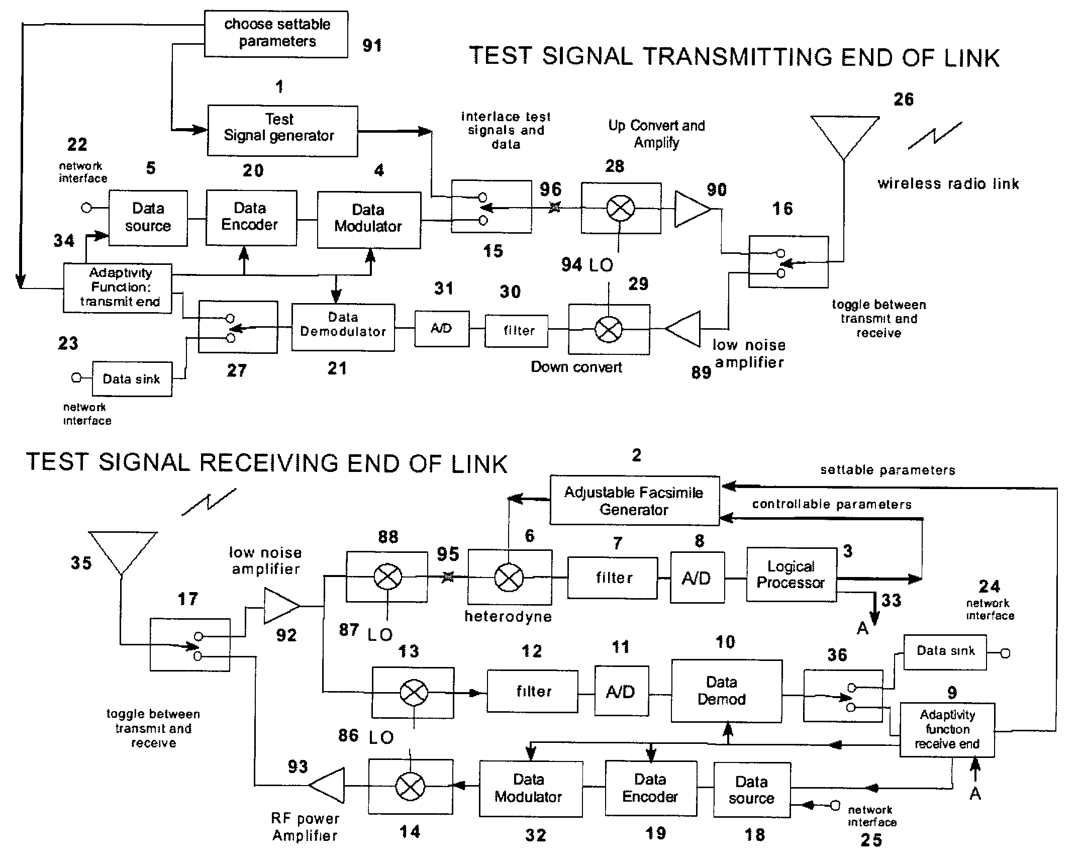
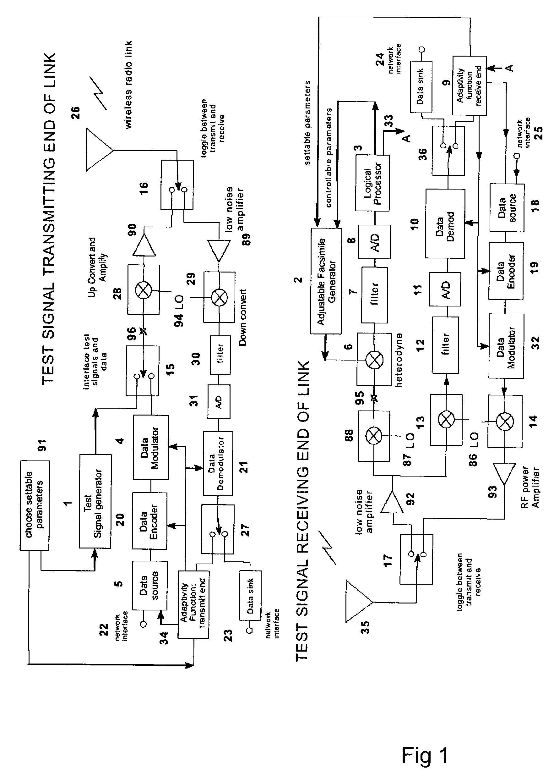
"The invention is a combination of a vector network analyzer and an adaptive wireless communication link that improves network efficiency and quality of service. The vector network analyzer provides crucial information for adaptivity functions at both ends of the link, while the adaptive wireless communication link uses the information to modify control parameters in the data demodulators and encoders. The invention takes advantage of duality in the wireless propagation links and stability of the internal circuitry to improve network performance. The invention also includes a piggy-back function of a numerical file with channel information, which allows for quick updates to settings in the wireless link. The test signal is a composite of segments of linear FM sweeps, and the invention provides settable parameters for the generators at both ends of the link."

Problems solved by technology

Getting around the problem of using cables to connect to a conventional VNA is not easy, but has been done before.
In this Application, the unwanted rotations are called artifacts, removal of which is described in DETAILED DESCRIPTION section 3.The received measurement probe signal in a wireless transmission channel will be noisy, and may need to be filtered or processed before it can be useful.Slow, stepped-frequency signals used in network analyzers are totally inappropriate for transmission over a communications network with thousands of subscribers, since this signal will interfere with data communications packets.Subscriber equipment must be inexpensive, so the equipment-related errors described above, namely φ(t), τε, Δf / f, and fε, may be very significant especially soon after the subscriber first turns on the receiver.

Method used


Image

  • Vector network analyzer applique for adaptive communications in wireless networks
  • Vector network analyzer applique for adaptive communications in wireless networks
  • Vector network analyzer applique for adaptive communications in wireless networks

Examples


Embodiment Construction

[0133]1. Preferred Embodiment

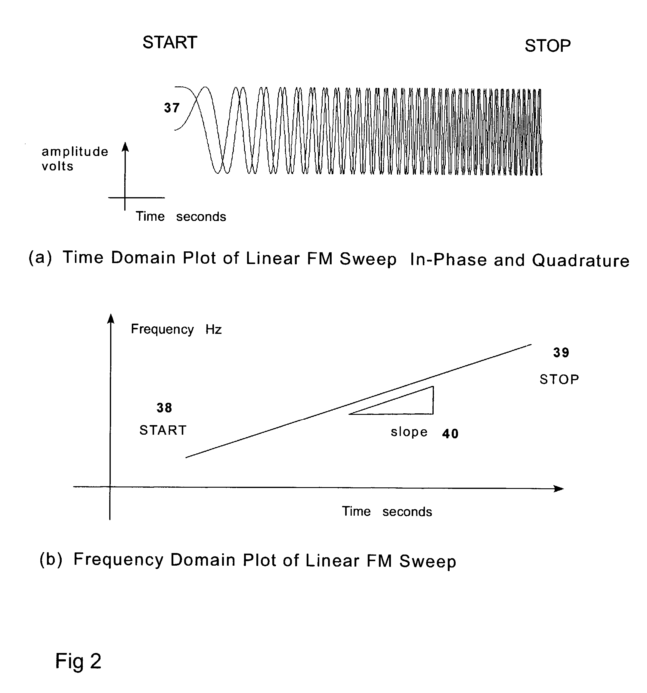
[0134]In this description, the preferred embodiment uses test signals that are segments of linear FM sweep signals. Many combinations of such signals are possible. The nature and benefits of the invention are not dependent on the precise format and placement of linear FM sweep signals, so there may be many variations in how the sweep signals are interlaced with communications. Additional embodiments such as the use of CDMA test signals are also possible and will be described in section 5.

[0135]The underlying purpose and benefit of the invention is its ability to compute, distribute and make use of, a frequency transfer function for each individual link in a wireless network subject to fading channel conditions.

[0136]At the start of the procedure envisioned for any typical use of the invention, there is a two-step process called acquisition and tracking which is independently performed in each receiver while a transmitting station broadcasts test signals ...


PUM


Abstract

A test signal generator at a transmitter station and a facsimile generator at a receiver station go through an acquisition and tracking process which aligns the two signals so that a logical processor can compute the frequency transfer function of the entire propagation path for use in an adaptive, concurrently sent communication signal. The frequency transfer function is conveyed back to the transmit end via a control channel permitting an adaptivity function at the transmit end to influence subsequent selection of communication parameters, among which are typically transmitted data rate, selection of modulation, selection of forward error correcting coding, and selection of frequency band for transmission. The same measurement is conveyed to an adaptivity function at the receive end for use in the communications receiver to select demodulator variables such as gain control, and equalization of amplitude and phase, versus frequency. The adaptivity function also permits interspersing of reverse-direction communications over the same frequency bands in a time-share mode between forward-direction and reverse-direction communication with the measurement signals having to be transmitted in only one direction. An alternate embodiment invention of this type is described which is additionally useful for mobile communications channels. Another variation embodiment is described for pure propagation measurements only, absent conveyance of end-user information.

Description

[0001]This application claims the benefit of Provisional Application No. 60 / 338,812, filed Dec. 12, 2001.BACKGROUND OF THE INVENTION[0002]1. Field of the Invention[0003]The present invention relates generally to a wireless communication channel and more particularly to a channel measurement technique that is employed concurrent with communications. All classes and subclasses listed in this section were obtained by searching the USPO web site. Most recent search: October 2002.[0004]The invention combines a novel way to realize a vector network analyzer (class 324 / subclass 615, 607, 606) and a communications link, the former operating concurrent with the latter, in such a way that information about the channel behavior is supplied directly and expeditiously to an adaptivity function associated with operating the communication link over a fading channel.[0005]Examples of adaptivity aided by this invention are, adjusting the data rate, center frequency, type of modulation, bits per seco...

Claims


Application Information

Patent Timeline
Patent Type & Authority Patents(United States)
IPC IPC(8): H04B17/00H04L1/00H04L1/24H04L25/02
CPCH04L1/0001H04L1/244H04B17/20H04B17/15H04L25/022
Inventor EBERT, PAUL MICHAELARNSTEIN, DONALD STUART
Owner SARABAND WIRELESS
Learn More