
Computer operation management system

Inactive Publication Date: 2006-12-26
HITACHI LTD
View PDF40 Cites 6 Cited by
  • Summary
  • Abstract
  • Description
  • Claims
  • Application Information

AI Technical Summary

Benefits of technology

[0009]An object of the present invention is to provide a method and a program, and furthermore, a computer or a system using the same in a computer system to which a plurality of computers are connected, in which a managing computer for managing these computers manages operations executed by the respective computers in a batch mode, and the managing computer can execute operating of the operations and managing of the computers themselves in relation to each other, and a problem occurring in the operations process can be readily solved in relation to a problem occurred in the computers themselves and in a communication network.
[0010]Another object of the present invention is to provide a method and a program capable of avoiding an excessive load on the communication network, and to provide a computer, or a system with employment of this method and program.
[0015]means for mutually switching a monitor screen displayed by the operation monitoring means and a monitor screen displayed by the computer monitoring means to display the switched monitor screen, while making a relationship between the computers and the operations executed on the computers, and also for clarifying the relationship among the operations and the computers;

Problems solved by technology

However, if the above-mentioned conventional computer systems are applied to such a lange-scale computer system, then a total operation management could not be practically realized as a computer system.
In addition, since the respective operation processes are independently operated and both the computers and the communication network are separately managed, it is practically difficult to solve the problem occurring in the operation processes in correspondence with the problem occurring in the computers.

Method used


Image

  • Computer operation management system
  • Computer operation management system
  • Computer operation management system

Examples


Embodiment Construction

[0036]Referring now to drawings, various embodiments of the present invention will be described.

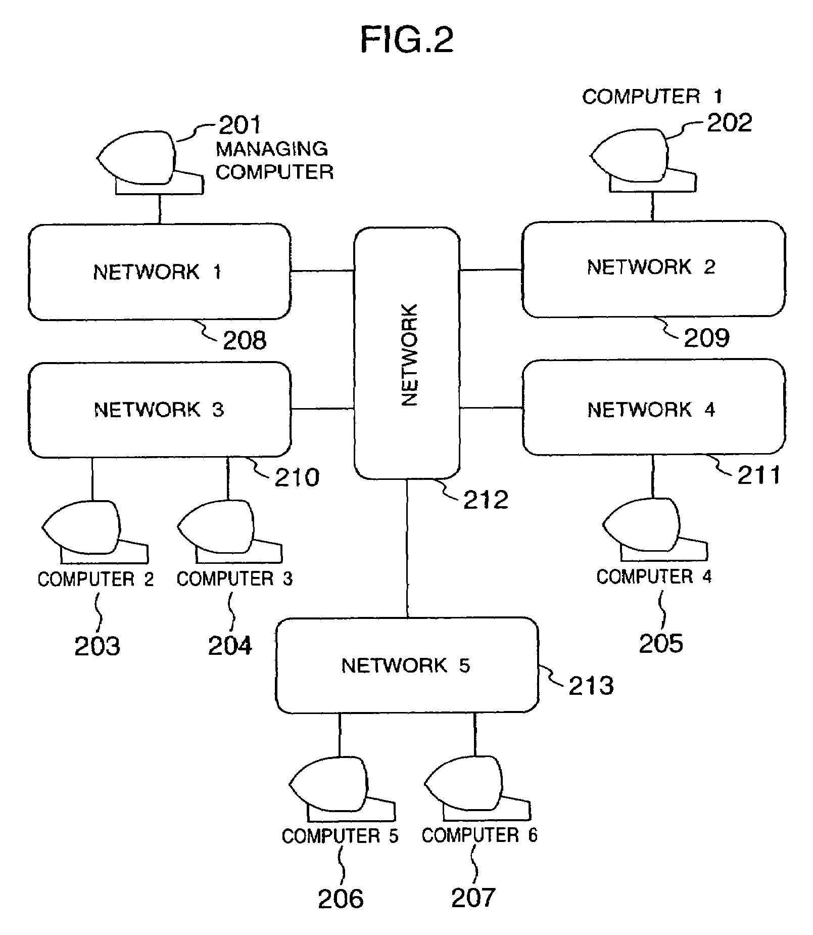
[0037]In FIG. 2, there is shown an overall arrangement of a computer system according to this embodiment. A managing computer 201 is connected via networks 208 to 213 to computers 202 to 207 which are to be managed by the managing computer.

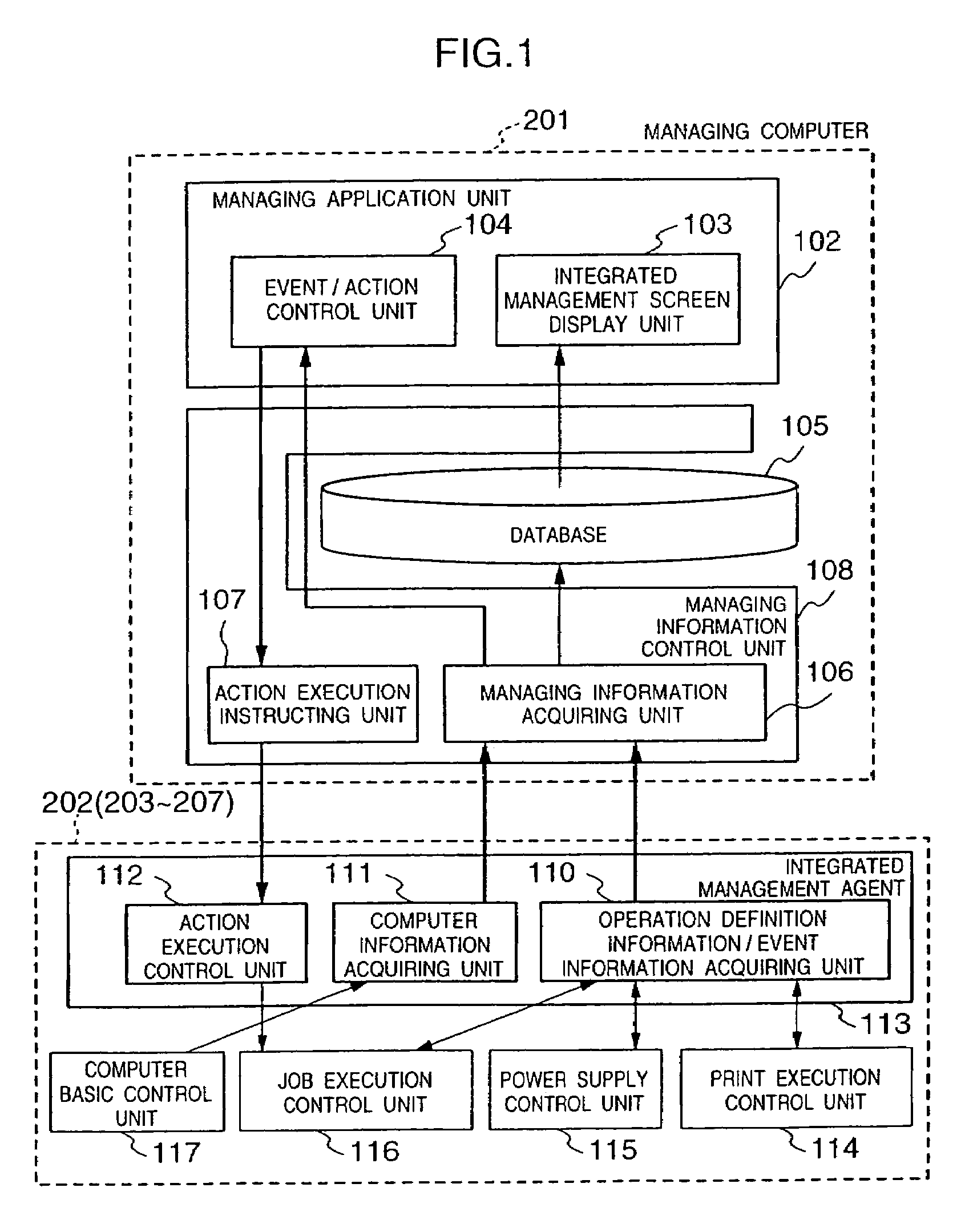
[0038]The computer system according to this embodiment allows the managing computer to collectively manage operation definition information, execution conditions, and execution results in combination with conditions of the computers themselves and the networks. In the operation definition information, execution schedules of operation processes are defined which should be executed by the computers 202 to 207. The execution conditions and the execution results are related to the computers 202 to 207.

[0039]FIG. 1 represents a system structure used to realize an integrated management of the computers 202 to 207 by the managing computer. It should be noted t...


PUM


Abstract

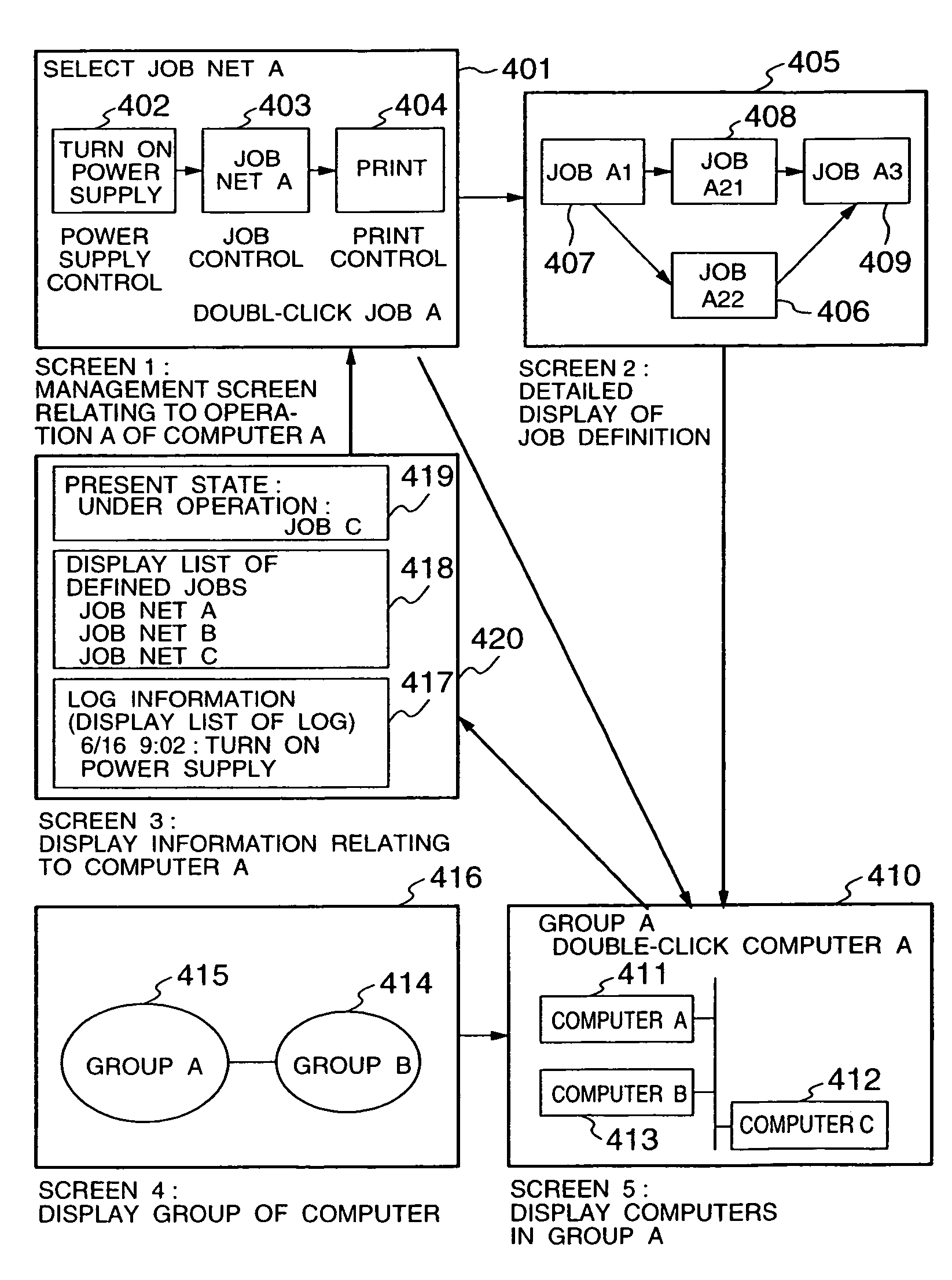
In a computer system to which a plurality of computers are connected, a managing computer manages operations performed in the respective computers in an integrated manner, or manages the operations in relation to the computers themselves. As a result, problems occurring in the processes can be easily solved, and furthermore a load on a network is reduced. The managing computer manages a series of operations in an integrated manner in which when an operation is executed by each of the plurality of computers, or by the respective computers in combination with each other, the managing computer performs an operation designated when a specific event happens to occur on a computer. The managing computer displays each of the operations executed on the computers by a symbol; displays an execution sequence of the operations by a link with a direction among symbols; and further displays an execution condition of the computer by a color of a symbol. As a consequence, both an operation monitor screen and a computer monitor screen are mutually switched to display the switched monitor screen while setting a relationship between the computers and the operations, and the relationship between the operations and the computers are clearly represented.

Description

[0001]This is a continuation of application Ser. No. 09 / 188,263, filed Nov. 9, 1998 now U.S. Pat. No. 6,170,010.BACKGROUND OF THE INVENTION[0002]The present invention relates to a computer operation management system in which a plurality of computers are connected via a network to a managing computer for managing these computers.[0003]Japanese periodicals “NIKKEI COMPUTER” (issued on Jan. 22, 1996, in pages 115 to 117), and “NIKKEI OPEN SYSTEM” (issued in June, 1997, No. 51, pages 234 to 239) describe the following conventional computer systems. That is, in these conventional computer systems, the functions for executing the operation processes are provided as independent programs. As the operation processes, there are the controls of turning ON / OFF the power supply, the job execution control, the print control, and the like. Also, these Japanese periodicals describe that the function for managing the conditions of the computers and the communication network is provided as a program...

Claims


Application Information

Patent Timeline
IPC IPC(8): G06F15/173
CPCH04L12/24H04L12/2602H04L41/00H04L43/00H04L41/046H04L41/22H04L43/0817
Inventor HIRATA, TOSHIAKIURANO, AKIHIROFUJINO, SHUJIMATSUMURA, EIJI
Owner HITACHI LTD
Learn More