Outdoor multi-method cooker

a multi-method cooker and outdoor technology, applied in the field of outdoor multi-method cookers, can solve the problems of reducing the effect of radiation heat transfer, charring and burning food, and inadequate control of grills,

Inactive Publication Date: 2007-01-02
CHURCHILL III ALBERT B +1
View PDF15 Cites 109 Cited by
  • Summary
  • Abstract
  • Description
  • Claims
  • Application Information

AI Technical Summary

Benefits of technology

[0017]It is therefore an object of the present invention to provide an outdoor multi-method cooker capable of preparing a wide variety of different foods at the same time using selective convection, radiant, or conduction cooking operations with or without smoke, or combinations thereof, using a single heat source.

Problems solved by technology

However, a common problem with these types of cookers and grills is that grease, sauce and drippings from the food being cooked and other combustible particles fall directly into the charcoal, lava rock, or fire, causing flare ups and hot spots within the grilling chamber and irregularities in cooking temperatures which can result in charring and burning of the food.
Many of these types of grills do not adequately allow a means for regulating the intensity of heat needed to properly grill various foods.
Reducing the temperature of the heat source can diminish the effect of radiation heat transfer and leave only relatively inefficient convection heating to cook the food.
Air blowers and plenum chambers have also been used to force air past the heat source to improve heat transfer efficiency, however, with many of these types of cookers, after the air is forced past the food product it is exhausted to the atmosphere and no longer redistributed within the apparatus to aid in the grilling process or for other cooking operations.
The achievement of uniformly cooked meat and the efficient use of fuel and energy are some continual problems associated with the operation of outdoor cookers and grills.
Although this patent recirculates hot air within the enclosure of the barbecue, it is only adapted for a heating element and not for wood or charcoal.

Method used


Image

  • Outdoor multi-method cooker
  • Outdoor multi-method cooker
  • Outdoor multi-method cooker

Examples


Embodiment Construction

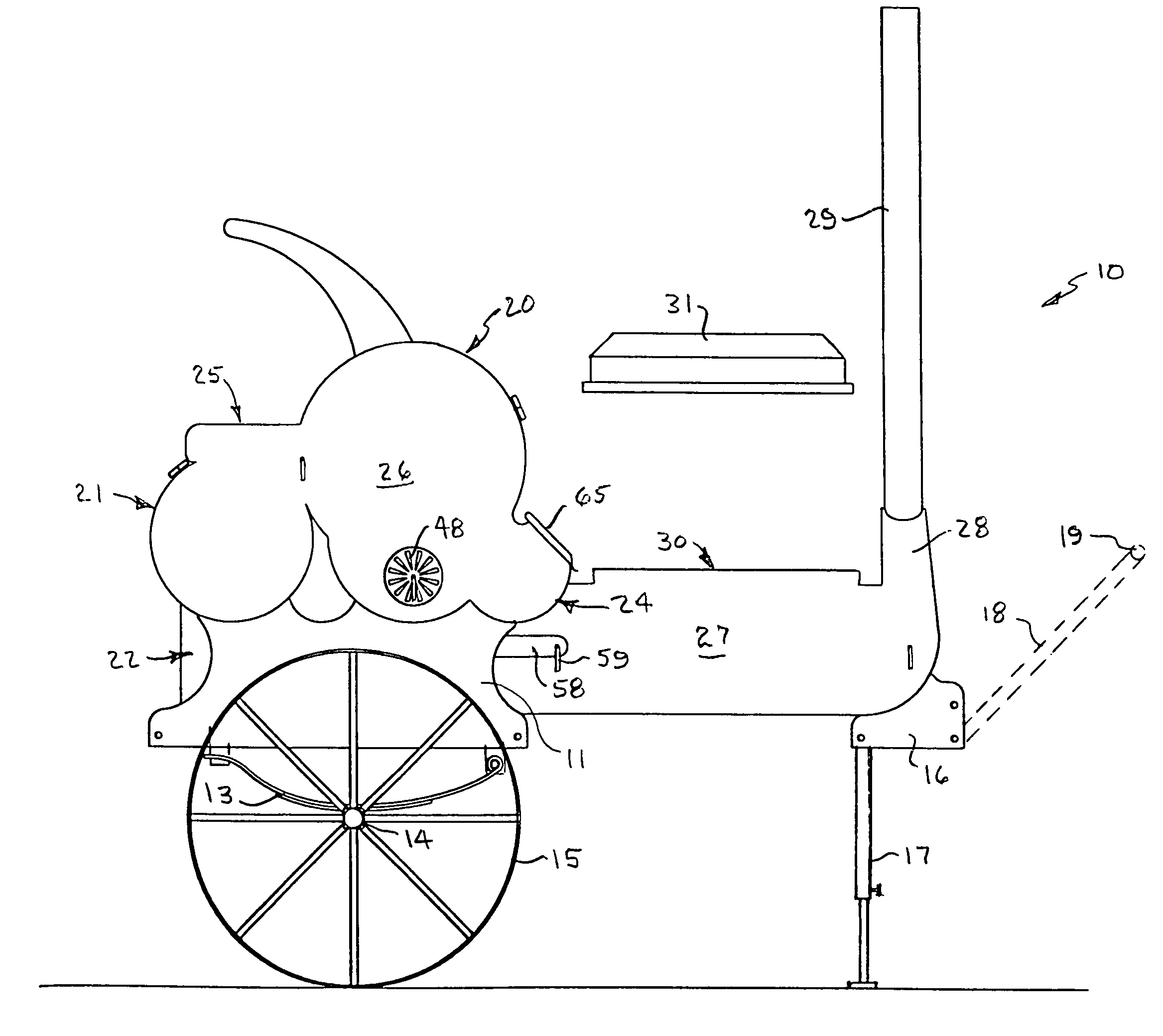
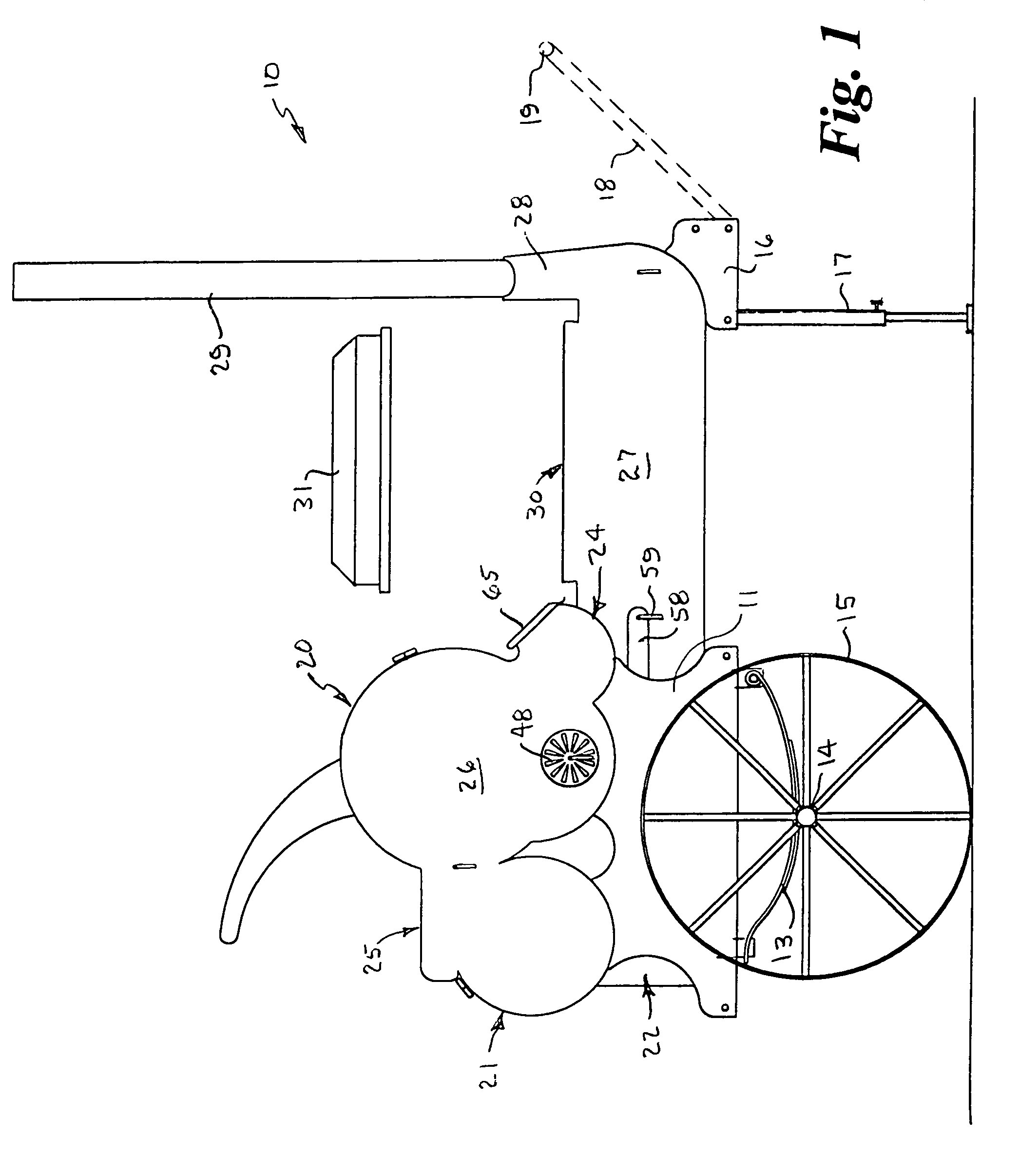
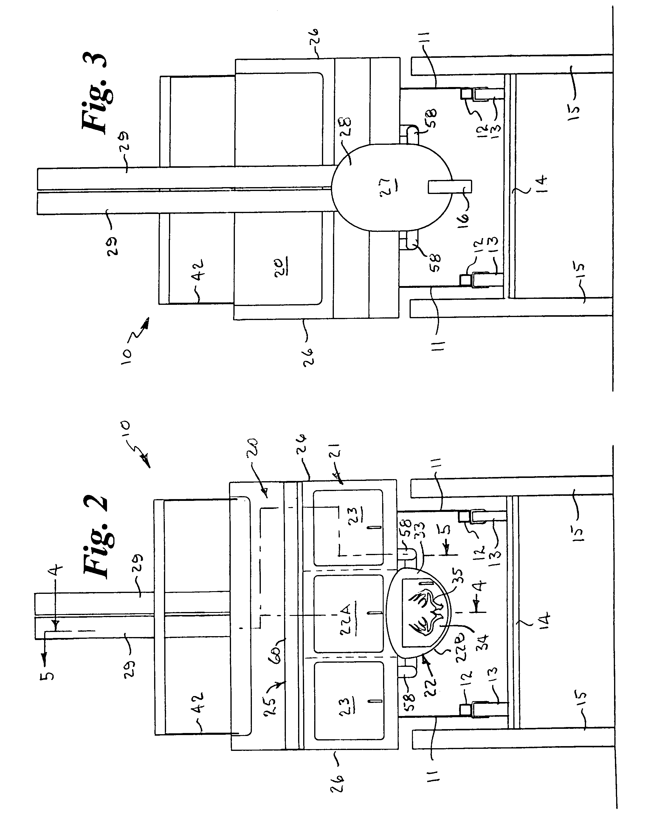
[0035]Referring to the drawings by numerals of reference, there is shown in FIGS. 1–3, a preferred outdoor multi-method cooker 10. In the following discussion, the terms forward or front refer to the direction or end of the cooker shown on the right-hand side of the figure as seen in FIG. 1. The terms rearward or rear refer to the direction or end of the cooker shown on the left-hand side of the figure as seen in FIG. 1.

[0036]The present cooker may utilize wood, charcoal, or charcoal and wood chips as the fuel source. Wood produces smoke, and charcoal alone produces some small amount of smoke, but much less than wood. In the following discussion, it should be understood that the phrase “smoke laden hot gases” is used to describe the products of combustion using wood, or charcoal with wood chips, as the fuel source, and “hot gases” is used to describe the products of combustion using only charcoal or a source that produces very little or no smoke.

[0037]The components of the cooker 10...


PUM


Abstract

An outdoor multi-method cooker for preparing a wide variety of different foods at the same time using selective convection, radiant, or conduction cooking operations with or without smoke, or combinations thereof, using a single heat source. The cooker has a horizontal central longitudinal chamber with a firebox at one end and a pair of stacks at the opposed end, a main oven, a pair of lateral smokeless ovens, a warming compartment, and a griddle above the firebox, all disposed transversely on the longitudinal chamber in parallel spaced relation, and a steam table along the upper portion of the longitudinal chamber. The cooker operates on the principle of equalization of natural differential pressures caused by rising warmer air, similar to the draw created by the upper portion of a fireplace, for drafting hot gases or smoke laden hot gases from the combustion source and selectively routing it through passageways into and around the various components.

Description

BACKGROUND OF THE INVENTION[0001]1. Field of the Invention[0002]This invention relates generally to outdoor kitchens and cookers, and more particularly to an outdoor multi-method cooker for preparing a wide variety of different foods at the same time using selective convection, radiant, or conduction cooking operations with or without smoke, or combinations thereof, using a single heat source.[0003]2. Background Art[0004]Mobile outdoor kitchens and cookers for cooking different foods at the same time are known in the art. In the early 1900's wheeled “rolling military kitchens” or “Field Kitchens” such as disclosed in Gunn, U.S. Pat. No. 1,244,489, Baldwin, U.S. Pat. No. 1,328,071 and Morrison, U.S. Pat. No. 1,422,603, were developed for feeding army troops.[0005]Barbecue grills have become increasingly popular in recent years because of the interest in outdoor cooking. Conventional charcoal grills utilize a quantity of charcoal placed in the lower portion of the grill with a cooking...

Claims


Application Information

Patent Timeline
Patent Type & Authority Patents(United States)
IPC IPC(8): A47J37/00
CPCA47J37/0704A47J27/04
Inventor CHURCHILL, III, ALBERT B.CHURCHILL, ROBERT S.
Owner CHURCHILL III ALBERT B
Why Eureka
Try Eureka