Heat pipe type cooler

Inactive Publication Date: 2007-01-02
FUJITSU LTD
View PDF42 Cites 20 Cited by
  • Summary
  • Abstract
  • Description
  • Claims
  • Application Information

AI Technical Summary

Benefits of technology

[0013]The primary object of the present invention is, therefore, to provide a integrally constructed cooler of the heat pipe type, which is free from the aforementioned drawbacks and which ensures

Problems solved by technology

Preferably, the heat radia

Method used


Image

  • Heat pipe type cooler
  • Heat pipe type cooler
  • Heat pipe type cooler

Examples


first embodiment

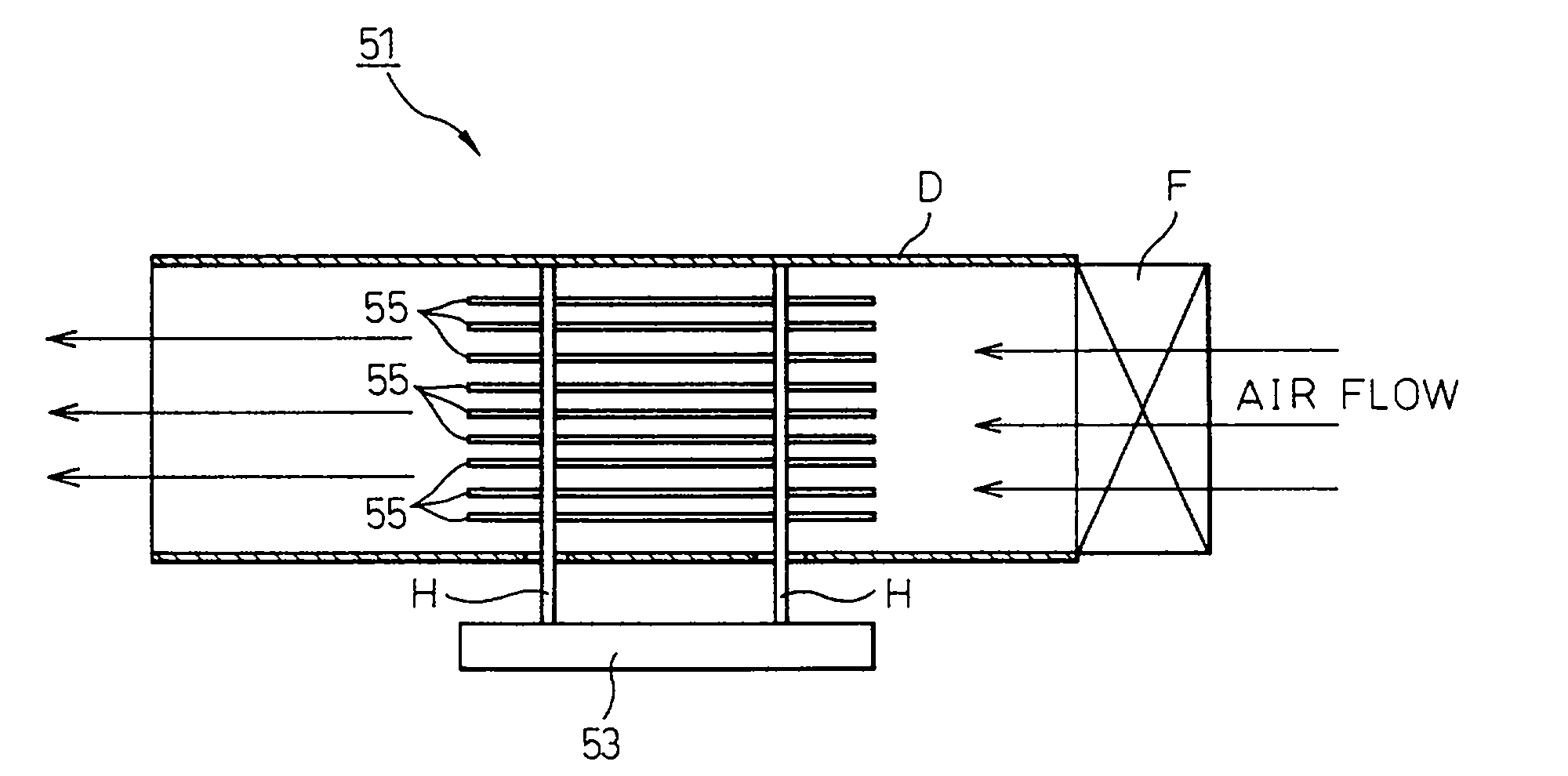
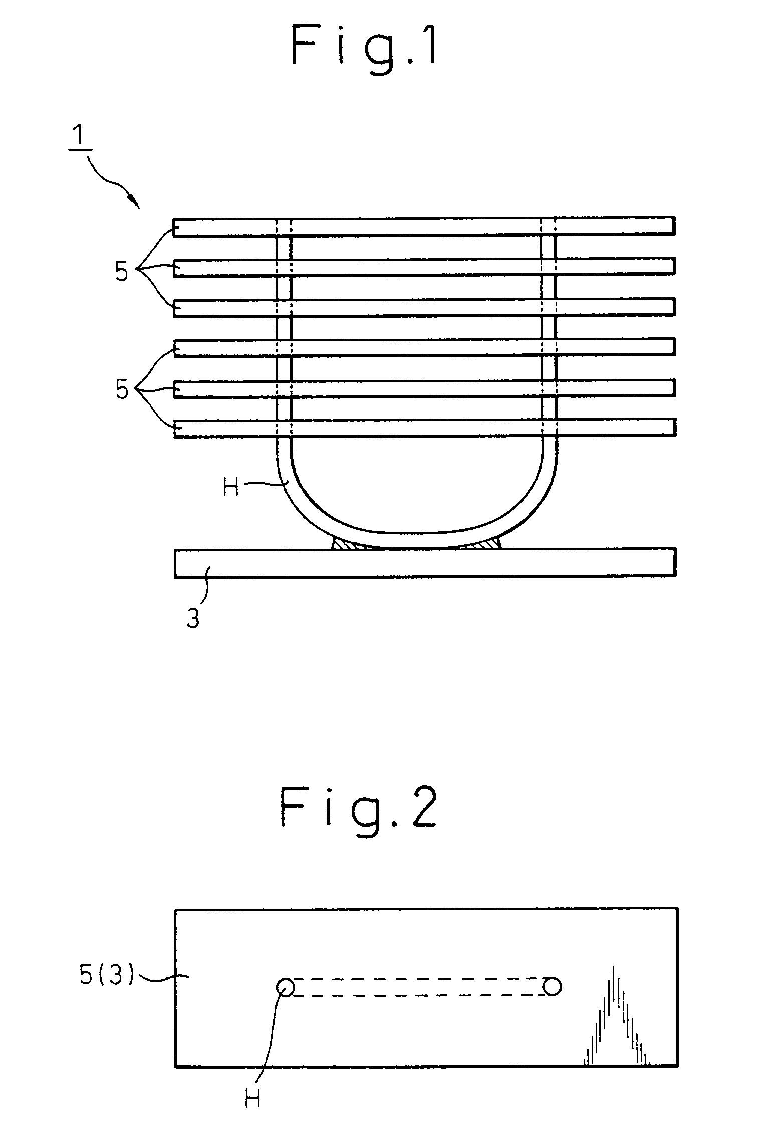
[0035]FIGS. 1 to 4 show heat pipe type cooler according to the invention.

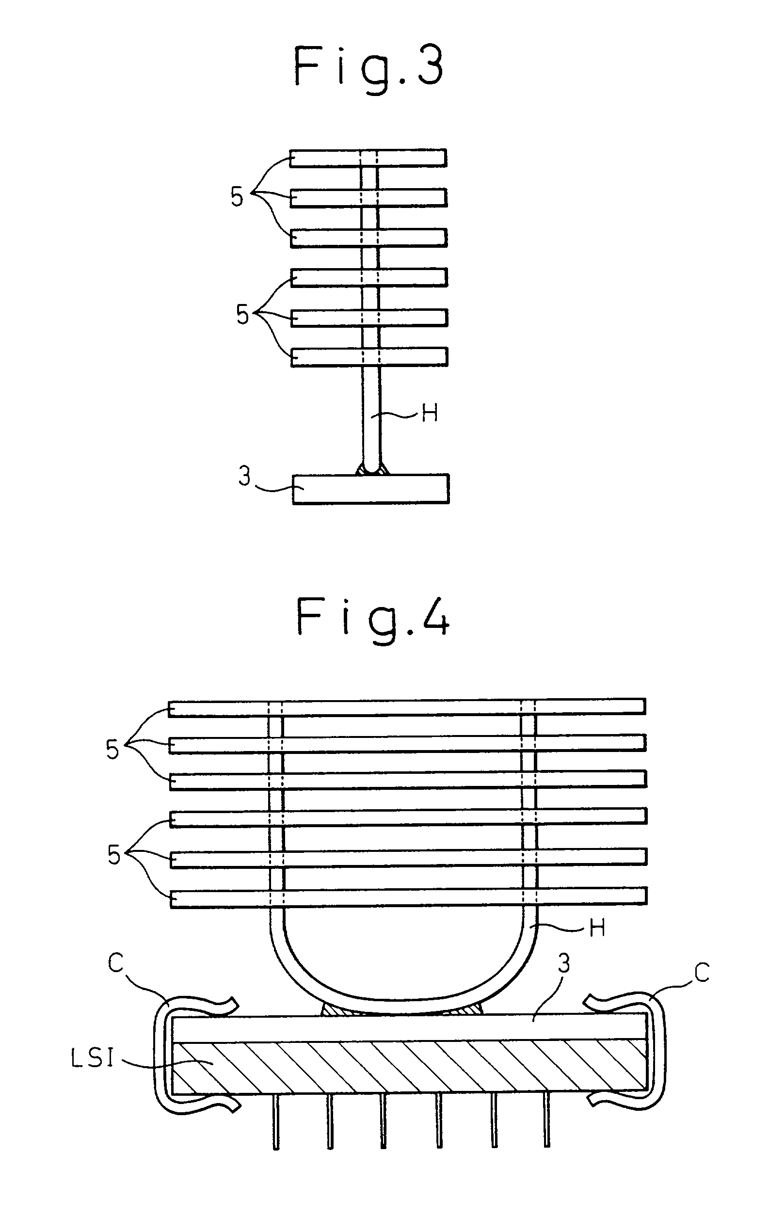
[0036]With reference to these drawings, the cooler 1 includes a rectangular, heat receiving plate 3 adapted to be fixed to an element (including a heat generator), not shown, intended to be cooled, and also includes a generally U-shaped heat pipe H. Instead, as shown in FIG. 5, a heat pipe H (composing another cooler 1′) may have a profile resembling a letter V, the intermediate portion of which being not sharp but round, so as to compose another type of cooler 1′.

[0037]As seen in FIG. 1, the intermediate, curved portion of the heat pipe H is fixed to the center on an upper surface of the heat receiving plate 3.

[0038]The heat pipe H has upstanding end portions in parallel with each other. Both of the heat pipe end portions pass through a heat radiator 5. The heat radiator 5 has a configuration of a number of (in this embodiment, six) horizontally oriented heat radiation plates (or fins) extending vertically. Th...


PUM


Abstract

To realize a integrally constructed cooler of the heat pipe type which ensures the achievement of sufficient cooling capacity and the realization of a simple, compact and inexpensive cooler, that is especially low in height, employing and incorporating ingeniously a heat pipe, there is provided a heat pipe type cooler comprising: a heat receiving plate 3; a heat radiator having a configuration of a plurality of horizontally oriented heat radiation plates 5 extending vertically; and a heat pipe H having a generally U or V shaped profile, the middle portion of which is secured to the heat receiving plate 3: and wherein each end of the heat pipe H passes through the heat radiation plates 5.

Description

BACKGROUND OF THE INVENTION[0001]1. Field of the Invention[0002]The present invention relates to a heat pipe type cooler.[0003]2. Description of the Related Art[0004]At present, technologically advanced and miniaturized electronic equipments are appearing. This involves a serious problem of internally generated heat at a high temperature. Use of a heat pipe has been considered and examined for the purpose of efficiently transferring such heat.[0005]A heat pipe is a heat-transfer device comprising a sealed metal tube of a generally straight bar shape, with an inner lining of a wicklike capillary material and containing a small amount of fluid (condensed fluid) in a partial vacuum. A heat is absorbed at one end by vaporization of the fluid and is released at the other end by condensation of the vapor. A heat pipe is characterized by its simple structure and its a high heat transfer rate per unit area, and it can be used in a wide range of temperatures in response to requirements.[0006...

Claims


Application Information

Patent Timeline
IPC IPC(8): F28D15/00F28D15/02H01L23/427H05K7/20
CPCF28D15/0233F28D15/0275H01L23/427H01L2924/0002H01L2924/00
Inventor UEDA, AKIRASUZUKI, MASUMI
Owner FUJITSU LTD
Why Eureka
Try Eureka