Means and apparatus for microrefrigeration

a micro-refrigeration and apparatus technology, applied in the direction of domestic cooling apparatus, indirect heat exchangers, lighting and heating apparatus, etc., can solve the problems of increasing the heat dissipation level, requiring more input power than can be dissipated, and requiring more input power. to achieve the effect of sufficient cooling capacity and work more efficiently

Inactive Publication Date: 2003-12-04
THAR PROCESS
View PDF26 Cites 5 Cited by
  • Summary
  • Abstract
  • Description
  • Claims
  • Application Information

AI Technical Summary

Benefits of technology

[0015] It is therefore an object of this invention to provide improvements in the way small-scale refrigeration devices are designed and operated so as to make them work more efficiently and thereby to provide sufficient cooling capacity in a volume of space, small enough to allow such refrigeration devices to be incorporated within, or as part of, the enclosure of an electronic or other small-scale appliance.
[0017] Another object of the present invention is to derive power to operate the refrigeration device from the same public power source that drives the electronic or other small-scale appliance, without requiring more power than that which is dissipated in the process of refrigeration.
[0018] Another object of this invention is to provide refrigeration capacity that is sufficient to extend the operating life of electronic components, or to increase the speed of operation of said components, over that which would be expected with conventional non-refrigeration means.
[0032] The apparatus as recited provides increased cooling capacity and increased energy efficiency over cycles operating with throttling valves.
[0033] Further aspects of the apparatus as recited is that it operates with a natural and environmentally benign working fluid that is oil-free. The said container does not exceed 10cm.sup.3 / watt of microrefrigeration for said container consuming 100 watts or lower. The apparatus may additionally include: one or more intercoolers to transfer useful work from the high pressure side to the low pressure side; one or more separators to separate gas from liquid; an ejector for throttling, wherein the said ejector is between heat exchangers. Said entercoolers, separators and ejector increase the efficiency of the cycle.
[0034] In the apparatus as recited, the compressor means, throttle control means, motor, or a combination thereof are regulated by a regulating means. Sensors monitor and control temperature and temperature-related phenomena. The apparatus derives power from a target device's public power network or the apparatus derives power from an independent source. Insulation avoids external condensation on the apparatus and it avoids external condensation on the target device.

Problems solved by technology

The need for increased performance of such devices, together with ever increasing compactness, has led to greatly increased levels of heat dissipation from these devices, with the consequence that the conventional forms of cooling are in many cases unable to prevent device temperatures from rising too high, causing the devices to fail.
Pettier coolers have the disadvantage of requiring more input power than can be dissipated and are therefore inefficient means of microrefrigeration.
However, no specific cooling medium is provided.
Refrigeration, as opposed to cooling, increases the complexity of design, especially if enclosing all components of the refrigeration cycle in a single container.
A disadvantage is that wire connections for signal transmission to and from the electronic components are discouraged and are instead substituted by optical connections in the preferred version of that invention.
Current systems for refrigerating electronic equipment are bulky and can add to the overall size of the electronic appliance.
The challenge in today's environment is to miniaturize such refrigeration systems so as to fit into existing appliance architecture, including laptop computers.
By the early 1970s, however, the environmental risks posed by CFCs, particularly to the atmosphere's ozone layer, were realized.

Method used


Image

  • Means and apparatus for microrefrigeration
  • Means and apparatus for microrefrigeration
  • Means and apparatus for microrefrigeration

Examples


example 1

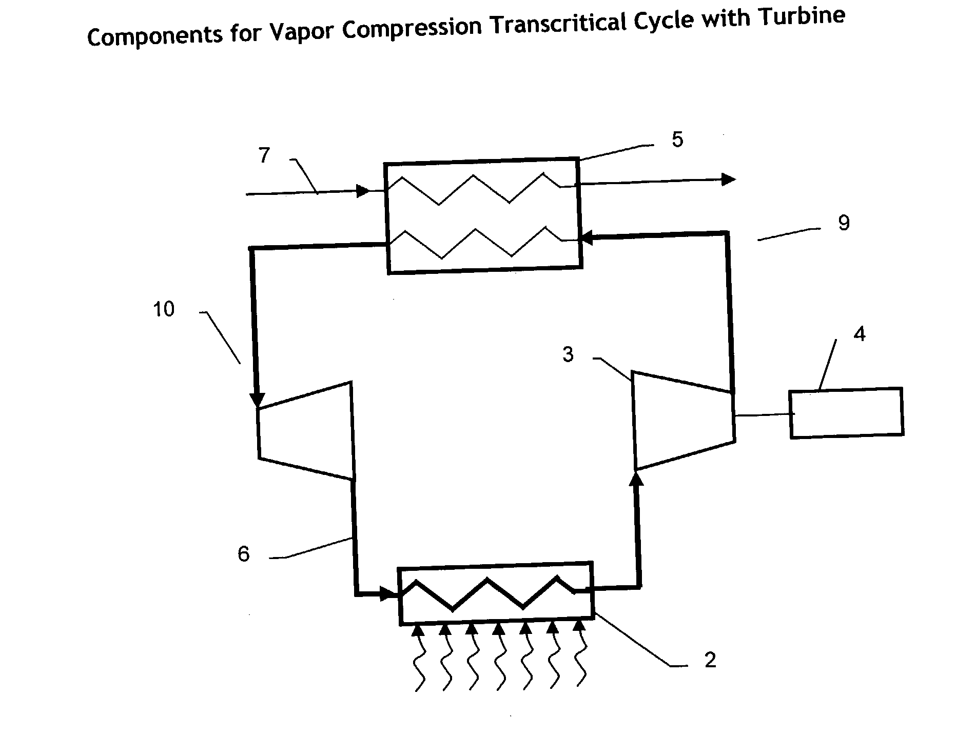
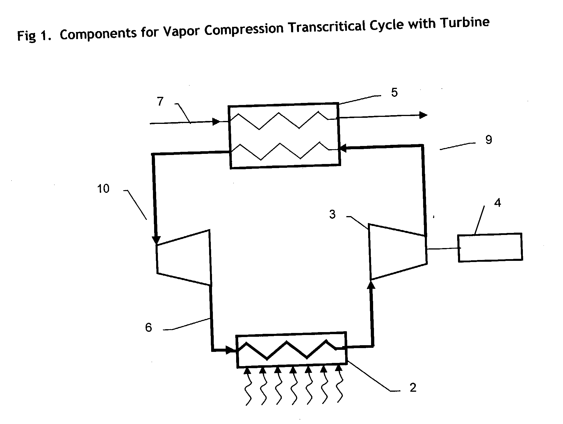
[0127] The COP of a cycle operating with a turbine in place of a throttling valve, without an intercooler, rises 28%, from 2.12 to 2.93, at constant evaporator temperature of 5.degree. C.

example 2

[0128] The COP of a cycle operating with a turbine and no intercooler can be improved more than two times, from 2.93 to 6.15, by allowing the temperature at the evaporator inlet (or turbine outlet) to rise from 5.degree. C. to 25.degree. C.

1TABLE 1 Refrigeration Performance by Cycle Type Condenser Evaporator Outlet Cycle description .degree. C. Bar .degree. C. Bar COP Throttling valve 5 39 40 98.6 2.12 Intercooler and throttling valve 5 39 40 98.6 2.26 Turbine in place of throttling 5 39 40 98.6 2.93 valve, no intercooler Turbine in place of throttling 30 71 50 103.6 1.04 valve, no intercooler Turbine in place of throttling 25 63.5 50 98.6 2.07 valve, no intercooler Turbine in place of throttling 18 53.9 40 98.6 4.56 valve, no intercooler Turbine in place of throttling 25 63.5 40 98.6 6.15 valve, no intercooler

[0129]

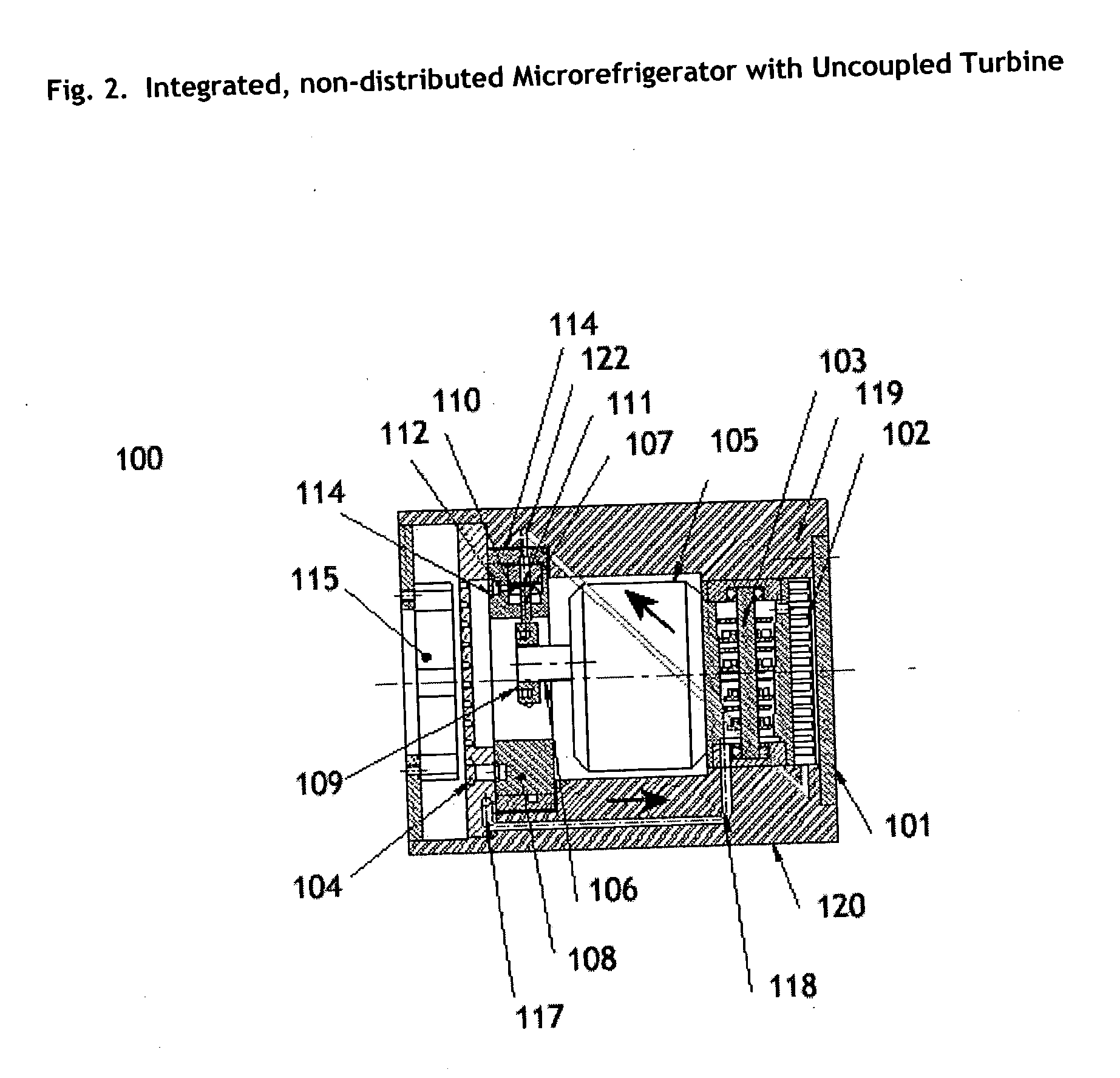
2TABLE 2 Annotation of Drawings 1 Cycle components 2 Heat accepter 3 Compressor 4 Motor 5 Heat rejecter 6 Working fluid 7 Ambient fluid 10 Turbine 11 Coupling shaft (op...


PUM


Abstract

An integrated, self-contained microrefrigeration apparatus, in a dimension small enough to fit inside small appliances, such as electronic cases and portable equipment is described. The microrefrigerator employs a working fluid that circulates between evaporator, compressor, condenser and turbine-expander components in a closed loop. Two configurations are claimed: one with the compressor and turbine operating on independent shafts, and the other with the turbine and compressor both operating on the motor shaft.

Description

CROSS-REFERENCE TO RELATED APPLICATION:[0001] This application claims priority to U.S. Provisional patent application Ser. No. 60 / 359,032 filed Feb. 22, 2002, teachings of which are incorporated herein by reference.[0002] 1. FIELD OF THE INVENTION[0003] This invention relates to refrigeration devices and methods that employ a supercritical fluid in a vapor-compression thermodynamic cycle, and more particularly to a small-scale apparatus needed to operate such a cycle. Typical applications include cooling of electrical, electronic, optical and portable devices.[0004] 2. Background[0005] Small-scale refrigerators, also referred to as microrefrigerators, are under development for the purpose of cooling such devices as computers, servers, telecommunications switchgear and numerous other types of electronic equipment, as well as portable coolers, medical equipment and many more items that are generally compact in design, if not portable in practice. Until recently, these types of equipme...

Claims


Application Information

Patent Timeline
Patent Type & Authority Applications(United States)
IPC IPC(8): F25B1/00F25B9/00F25B9/06F25B11/04F25D9/00H05K7/14
CPCF25B9/008F25B11/04H05K7/1438F25B2400/15F25B2500/17F25B2309/061F25B1/00F25D9/00
Inventor CHORIDA, LALITMOYER, BRIANDAVIS, JOHN C.
Owner THAR PROCESS
Why Eureka
Try Eureka