Combined type evaporative cooling unit

An evaporative cooling and composite technology, which is applied in heating methods, household heating, space heating and ventilation details, etc., can solve the problems of insufficient cooling capacity of the unit, insufficient cooling capacity, large size of the unit structure, etc., and save water consumption. and power consumption, improvement of regional constraints, and small overall structure

Inactive Publication Date: 2016-03-09
农继荣
View PDF11 Cites 4 Cited by
  • Summary
  • Abstract
  • Description
  • Claims
  • Application Information

AI Technical Summary

Problems solved by technology

[0002] Dry air energy is a kind of clean renewable energy. In the case of increasingly depleted energy and increasingly harsh environment, it has been paid more and more attention, especially in Northwest my country where dry air energy is relatively abundant. However, the single use of dry air energy In addition, evaporative cooling technology also has the advantages of energy saving and environmental protection. Therefore, in recent years, many scholars have proposed to combine evaporative cooling technology with dry air energy, and this scheme has also been obtained. widely used
[0003] However, in practical applications, evaporative cooling technology itself also has many defects. For example, if direct evaporative cooling technology or indirect evaporative cooling technology is used alone, the unit will be limited by regional adjustment or insufficient cooling capacity; Under normal circumstances, the structure of the unit is relatively large and occupies a large area; moreover, in most cases, the use mode of an evaporative cooling unit is relatively single or the structure does not change, and the cooling capacity of the unit will be too much, resulting in a waste of energy

Method used


Image

  • Combined type evaporative cooling unit
  • Combined type evaporative cooling unit
  • Combined type evaporative cooling unit

Examples


Embodiment Construction

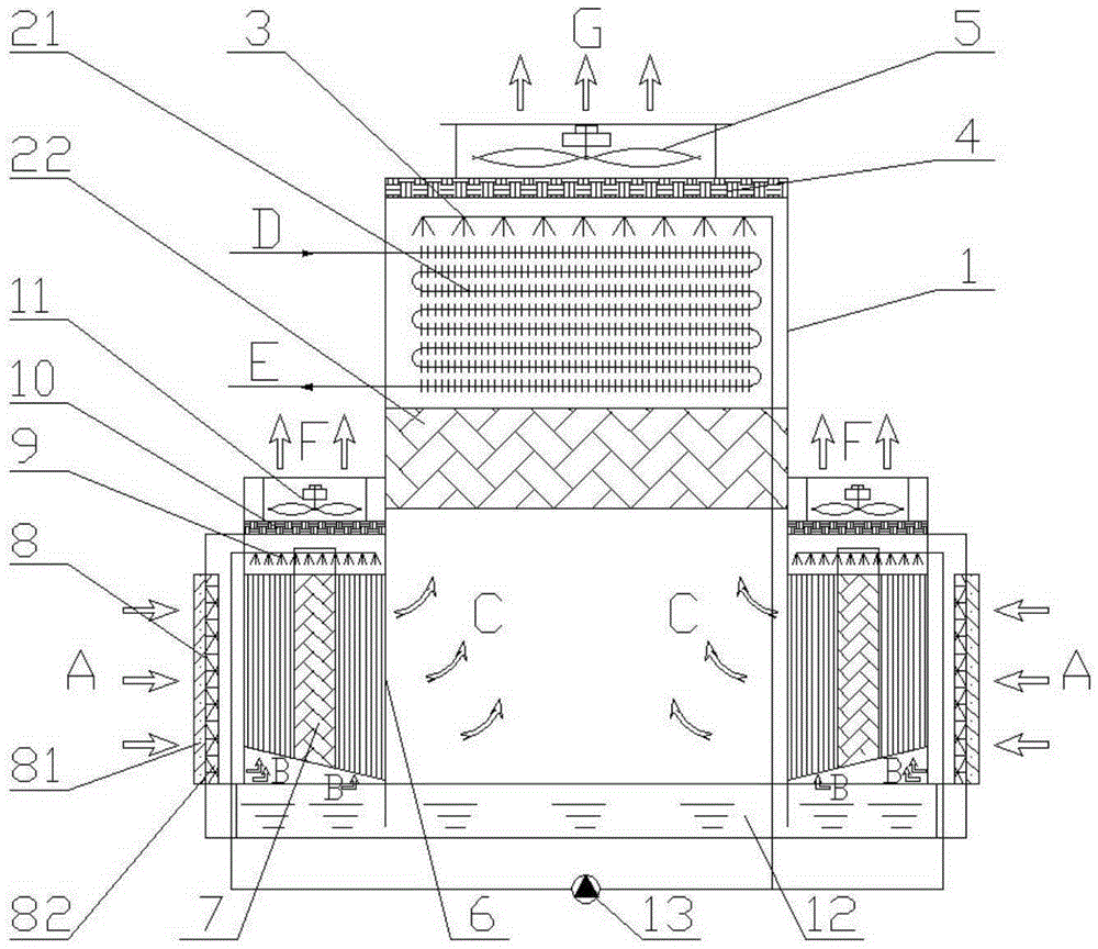
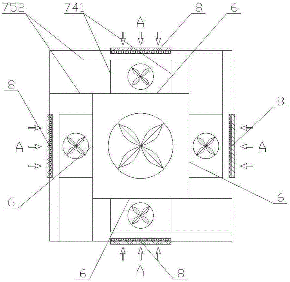
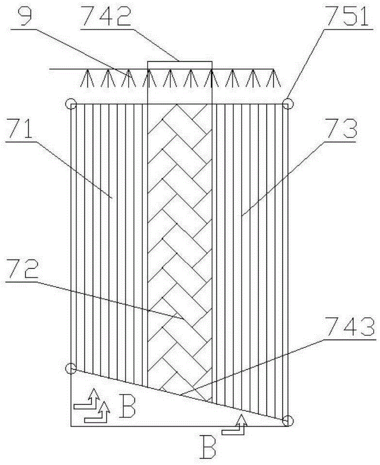
[0025] see figure 1 and figure 2 , in a preferred embodiment of the present invention, a composite evaporative cooling unit 100 includes a housing 1, the housing 1 contains a direct evaporative cooling module and four pre-cooling modules 7, and in the housing 1 is provided with a ventilation opening 8 that allows air to enter the unit 100; preferably, each pre-cooling module 7 is the same, and the ventilation opening 8 is arranged in the middle of each side wall, and The vents 8 are distributed symmetrically on opposite sides, especially, the position, shape and size of the openings of each vent 8 are the same. An air guiding device 81 and a filter 82 are sequentially installed on each vent 8 from the outside to the inside. Preferably, the wind guiding device 81 adopts the form of a rotatable shutter, so that each vent 8 can be selectively usage of. In addition, the outer shell walls of the housing 1 are made of heat-insulating materials and have a sealing effect.

[0026...


PUM


Abstract

The invention provides a combined type evaporative cooling unit. The unit comprises a shell, a direct evaporative cooling module and pre-cooling modules; the direct evaporative cooling module comprises a coiler heat exchanger and a first filler and is arranged inside the shell, the first filler is arranged below the coiler heat exchanger, and the coiler heat exchanger is sequentially provided with a first water distribution device and a first draught fan from bottom to top; the pre-cooling modules are arranged on two opposite sides of the shell and located below the first filler, one side of each pre-cooling module is provided with a communication opening communicated with the direct evaporative cooling module, and therefore air pre-cooled by the pre-cooling modules can flow into the direct evaporative cooling module; each pre-cooling module is formed by a vertical heat exchanger and a second filler; each pre-cooling module is sequentially provided with a second water distribution device and a second draught fan from bottom to top, and sliding devices capable of enabling the pre-cooling modules to slide are installed below the pre-cooling modules; and a ventilation opening is further formed in the lateral wall of the shell. By means of the sliding devices, the using manner of the unit is varied, the adaptability is good, and the practical performance is higher.

Description

【Technical field】 [0001] The invention relates to the field of refrigeration equipment, in particular to a compound evaporative cooling unit. 【Background technique】 [0002] Dry air energy is a kind of clean renewable energy. In the case of increasingly depleted energy and increasingly harsh environment, it has been paid more and more attention, especially in Northwest my country where dry air energy is relatively abundant. However, the single use of dry air energy In addition, evaporative cooling technology also has the advantages of energy saving and environmental protection. Therefore, in recent years, many scholars have proposed to combine evaporative cooling technology with dry air energy, and this scheme has also been obtained. Widely used. [0003] However, in practical applications, evaporative cooling technology itself also has many defects. For example, if direct evaporative cooling technology or indirect evaporative cooling technology is used alone, the unit will b...

Claims


Application Information

Patent Timeline
Patent Type & Authority Applications(China)
IPC IPC(8): F24F5/00F24F13/30
CPCF24F5/0035F24F13/30
Inventor 农继荣谢英健
Owner 农继荣
Why Eureka
Try Eureka