
Reduction device for nitrate determination

a nitrate and reduction device technology, applied in the direction of machines/engines, chemical/physical processes, combustion air/fuel air treatment, etc., can solve the problems of reducing difficult control, unfavorable kinetics of hydrazine reduction to nitrate, etc., to achieve the effect of reducing the nitrate to other species, reducing the nitrate to nitrate, and reducing the nitrate redu

Inactive Publication Date: 2007-01-02
THE UNITED STATES OF AMERICA AS REPRESENTED BY THE SECRETARY OF THE NAVY
View PDF4 Cites 20 Cited by
  • Summary
  • Abstract
  • Description
  • Claims
  • Application Information

AI Technical Summary

Benefits of technology

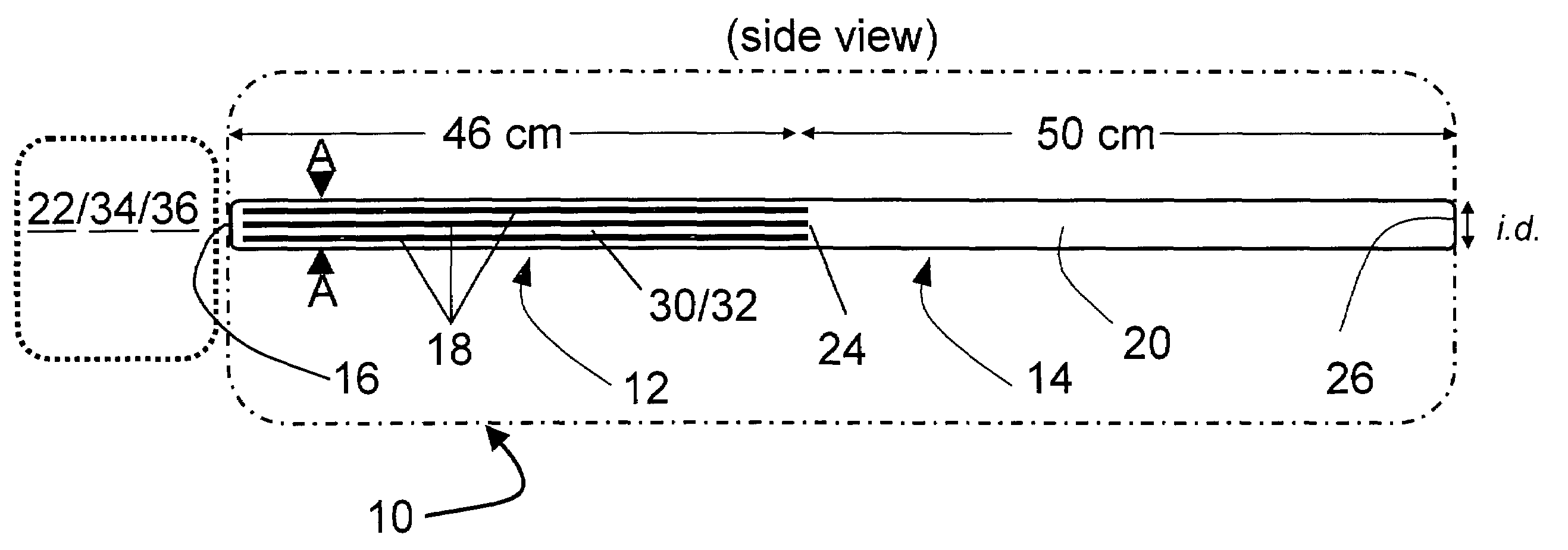
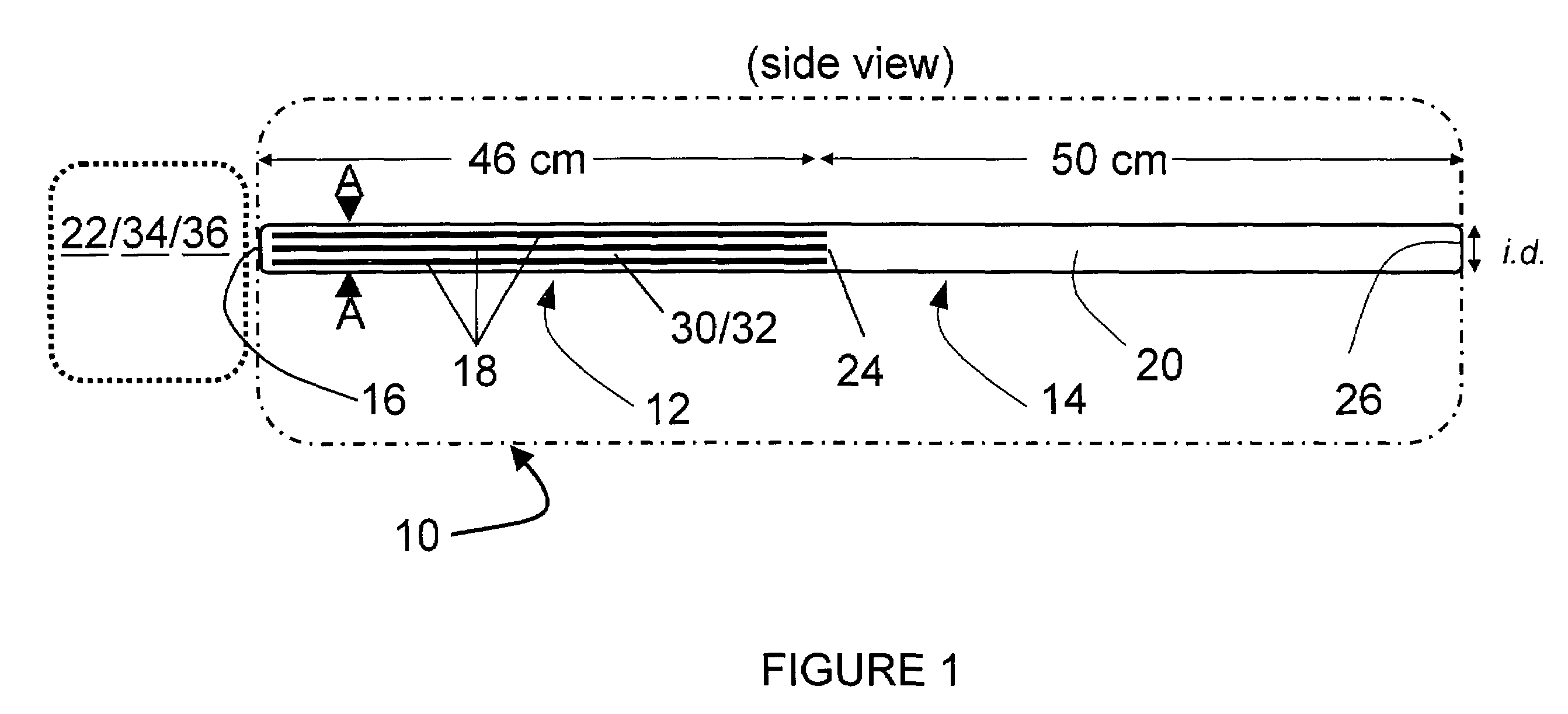
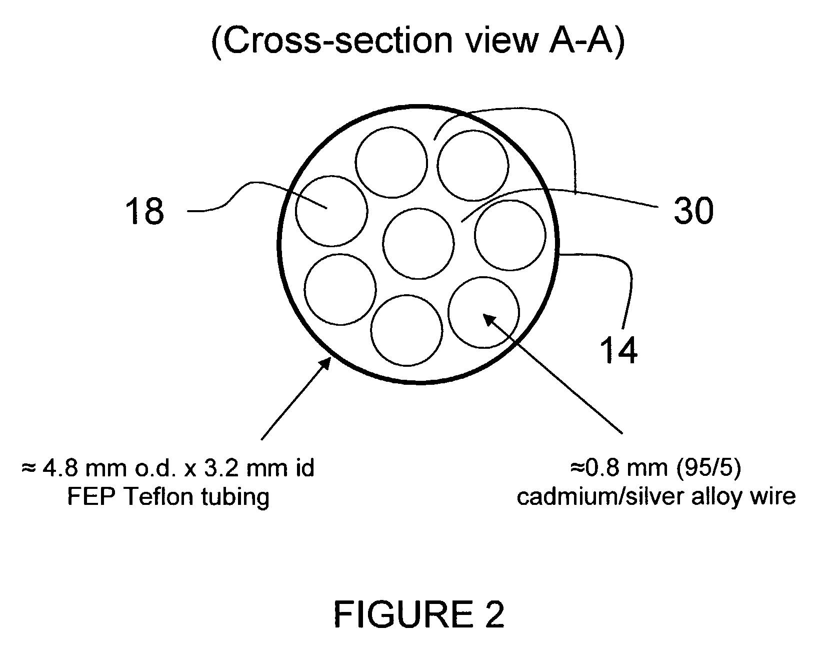
[0011]The present invention includes a nitrate reduction device comprising a reactor having a flow chamber having a first end for receiving a nitrate sample and a cadmium containing structure forming a plurality of longitudinal channels within the flow chamber. Preferably, the cadmium containing structure comprises a plurality of wires.

Problems solved by technology

Zinc provides a problematic reducing agent in that it is overly reactive resulting in reduction of nitrate to other species in addition to nitrite.
Reduction of nitrate to nitrite by hydrazine is kinetically unfavorable and difficult to control.
Bacterially derived nitrate reductase becomes inactive in air-saturated solutions and requires a hazardous cofactor.
Ultraviolet radiation is not kinetically favored and difficult to control.
Additionally ultraviolet radiation has power requirements to an ultraviolet lamp that may become prohibitive for remote applications.
Resistance to flow (back pressure) in packed-bed, granular cadmium reactor systems can also be problematic.
Additionally, the dissolution of cadmium granules that occurs as the granules react with nitrate and dissolved oxygen causes progressively increasing void volumes at the head of the reactor, adversely affecting reduction efficiency.
As such, none of these references address the need for high reactive surface-to-volume characteristics.
Aforementioned operability problems, including increased back pressure, increases as the size of cadmium granules decrease.
Thus an increase in reactor volume can only be achieved by increasing its length.
This characteristic leads to unacceptable amounts sample dispersion (dilution and loss of analytical detection) and back pressure for batch analyzer applications may require reduction systems with liquid volume capacities of several milliliters.

Method used


Image

  • Reduction device for nitrate determination
  • Reduction device for nitrate determination
  • Reduction device for nitrate determination

Examples


example 2

Void Volume of Multiple Strand, Wire-in-Tube Configurations

[0045]A 1-meter length section of 3.2-mm i.d. tubing is threaded with 8,1-meter lengths of 1-mm diameter cadmium / silver (95 / 5) wire. The surface-to-volume ratio equals 14.3 mm2 / microliter.

example 3

Void Volume of Multiple Strand, Wire-in-Tube Configurations

[0046]A 1-meter length section of 3.2-mm i.d. tubing is threaded with 8,1-meter lengths of 0.8-mm diameter cadmium / silver (95 / 5) wire. The surface-to-volume ratio equals 5 mm2 / microliter.

example 4

Void Volume of Multiple Strand, Wire-in-Tube Configurations

[0047]A 1-meter length section of 4 mm i.d. tubing is threaded with 10, 1-meter lengths of 1-mm diameter cadmium wire. The surface-to-volume ratio equals 6.7 mm2 / microliter.


PUM

PropertyMeasurementUnit
lengthaaaaaaaaaa
lengthaaaaaaaaaa
lengthaaaaaaaaaa

Abstract

A nitrate reduction device has a cadmium structure forming a plurality of longitudinal channels within a flow chamber, which may be formed by a plurality of wires. The device is used to reduce nitrate to a final nitrite product for analysis.

Description

STATEMENT REGARDING FEDERALLY SPONSORED RESEARCH OR DEVELOPMENT[0001]The invention described herein may be manufactured and used by or for the government of the United States of America for governmental purposes without the payment of any royalties thereon or therefor.BACKGROUND OF THE INVENTION[0002]1. Field of the Invention[0003]The present invention includes a nitrate reduction device for use on environmental monitors. The nitrate reduction device has a flow chamber containing a cadmium structure forming a plurality of longitudinal channels within the flow chamber. The cadmium structure may be formed by a plurality of cadmium containing wires.[0004]2. Brief Description of the Related Art[0005]Nitrite in natural water samples typically is determined colorimetrically using Griess reaction reagents, such as sulfanilamide and N-(1-Naphthyl)ethylenediamine. Equivalent specific and sensitive colorimetric reagents for nitrate determinations are not available. Therefore, nitrate is frequ...

Claims


Application Information

Patent Timeline
Patent Type & Authority Patents(United States)
IPC IPC(8): B01J8/18B01D47/00B01D47/16B01F3/04G01N15/06
CPCG01N33/1893G01N33/188
Inventor PATTON, CHARLES JOHNSTONROGERSON, PETER FREEMAN
Owner THE UNITED STATES OF AMERICA AS REPRESENTED BY THE SECRETARY OF THE NAVY
Learn More