Radar device and method for suppressing interference with a radar device

a radar device and interference suppression technology, applied in the field of radar devices, can solve problems such as ambiguities in the determination of target distances outside the unambiguous range of pulsed radar devices, and achieve the effects of suppressing interference effects, reducing the risk of overriding the i channel and/or the q channel due to mutual interference of radar sensors, and reducing interference effects

Inactive Publication Date: 2007-01-02
ROBERT BOSCH GMBH
View PDF11 Cites 19 Cited by
  • Summary
  • Abstract
  • Description
  • Claims
  • Application Information

AI Technical Summary

Benefits of technology

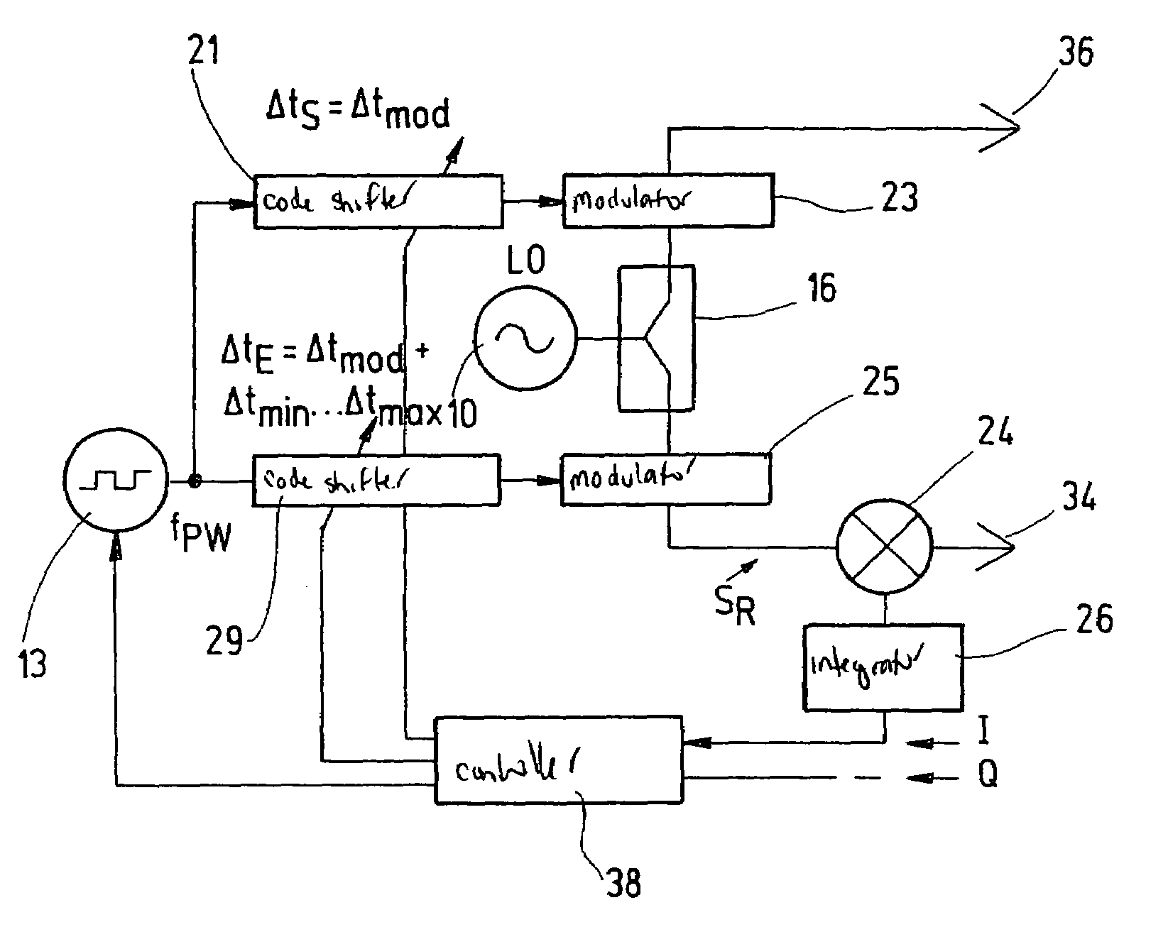
[0013]The present invention is particularly advantageous due to the fact that the arrangement to generate a pulse repetition rate fPW has a PN (“pseudo noise”) code generator and the arrangement to delay the pulses has an arrangement to code shift. When using such a discrete shift in a PN code, the delay of the modulation in the reference signal may be omitted. Negative values for the “delay” (advance) in the modulation in the transmission signal may be calculated in advance and / or adjusted with the help of the discrete code shift. Through the use of PN codes it is possible to improve the S / N ratio because it is possible to work at an increased pulse repetition rate with PN codes having a suitable autocorrelation function without causing any reduction in the maximum radar range.
[0027]The present invention is based on the surprising finding that interference due to transmission signals from other radar sensors, in particular similar radar sensors, may be suppressed by coding of the transmission point in time at the transmitter end. In addition, the risk of overriding of the I channel and / or the Q channel due to mutual interference of the radar sensors may be reduced. Likewise, signals from targets at target distances in the ambiguity range may be suppressed. This method is also advantageously applicable with radar systems which use already coded transmission signals and / or reference signals generated, e.g., with the help of PN coding by phase modulation and / or amplitude modulation. Furthermore, in the example embodiments, the length of the interval required for integration and / or averaging, e.g., in the case of PN coding, is not influenced. The cutoff frequency of a low-pass filter used for integration may thus remain unchanged and / or be selected with regard to an optimum value for the signal-to-noise ratio.

Problems solved by technology

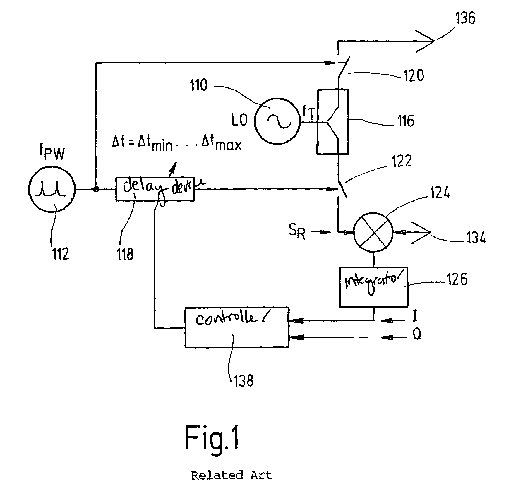
However, ambiguities may occur in the determination of target distances outside of the unambiguous range of a pulsed radar device.
In addition, there is interference due to multiple pulse radar sensors operating simultaneously when the sensors are operating within the range of another particular sensor.
There may be interference, i.e., for detection of apparent targets.

Method used


Image

  • Radar device and method for suppressing interference with a radar device
  • Radar device and method for suppressing interference with a radar device
  • Radar device and method for suppressing interference with a radar device

Examples


Embodiment Construction

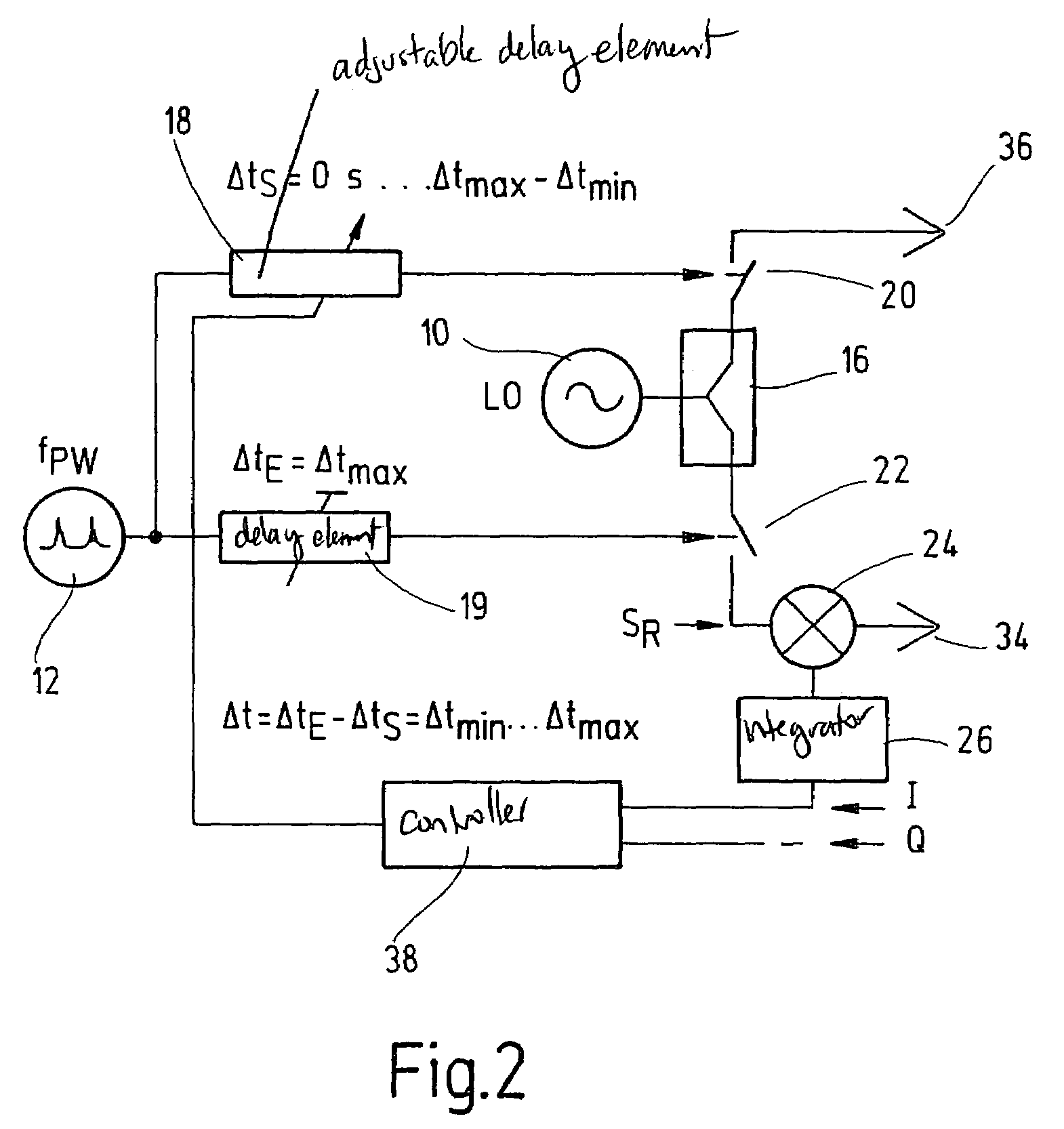
[0035]FIG. 2 shows a schematic diagram of a radar device according to an example embodiment of the present invention. A local oscillator 10 is connected to a power divider 16. This power divider 16 is connected to a transmission branch. Part of the power of local oscillator 10 is output by power divider 16 into the reception branch. Furthermore, a pulse generator 12 is provided for generating pulse repetition rate fPW. The output of the pulse generator is connected to an adjustable delay element 18 and to an adjustable or non-adjustable delay element 19. The output of adjustable delay element 18 actuates a switch 20 in the transmission branch for modulating the carrier signal. The output signal of the adjustable or non-adjustable delay element 19 actuates a switch 22 in the reception branch for modulating the carrier signal in the reception branch and thus for providing a reference signal SR. The signal modulated by switch 20 in the transmission branch is sent by sending aerial 36 a...


PUM


Abstract

A radar device is described having an arrangement to generate a carrier signal having a carrier frequency fT, an arrangement to generate pulses having a pulse repetition rate fPW, an arrangement to split the carrier signal between a transmission branch and a reception branch, an arrangement to delay the pulses, an arrangement to mix the carrier signal in the reception branch with a reception signal, and an arrangement to integrate the mixed signal. An arrangement to modulate the carrier signal in the transmission branch with the delayed pulses and an arrangement to alter the delay in the pulses according to a predetermined code are also provided. A method of suppressing interference with the functioning of a radar device is also described.

Description

FIELD OF THE INVENTION[0001]The present invention relates to a radar device having an arrangement to generate a carrier signal having a carrier frequency fT, an arrangement to generate pulses having a pulse repetition rate fPW, an arrangement to split the carrier signal between a transmission branch and a reception branch, an arrangement to delay the pulses, an arrangement to mix the carrier signal in the reception branch with a reception signal, and an arrangement to integrate the mixed signal. The present invention also relates to a method for suppressing interference with the functioning of a radar device, including generating a carrier signal having a carrier frequency fT, generating pulses having a pulse repetition rate fPW, splitting the carrier signal between a transmission branch and a reception branch, delaying the pulses, mixing the carrier signal in the reception branch with a reception signal and integrating the mixed signal.BACKGROUND INFORMATION[0002]Generic radar devi...

Claims


Application Information

Patent Timeline
Patent Type & Authority Patents(United States)
IPC IPC(8): G01S13/22G01S7/282G01S7/292G01S7/36G01S13/02
CPCG01S7/023G01S7/282G01S13/222G01S7/36G01S7/2921G01S7/0231G01S7/0234G01S7/0235
Inventor BROSCHE, THOMAS
Owner ROBERT BOSCH GMBH
Why Eureka
Try Eureka