Disc device with disc changer

a technology of disc changer and disc device, which is applied in the direction of data recording, recording head arrangement, instruments, etc., can solve the problems of high component price, heat generation and fire, and the magnetic field generated by the plunger has an effect on other components, and achieves the effect of secure positioning

Inactive Publication Date: 2007-01-02
ORION ELECTRIC CO LTD
View PDF21 Cites 13 Cited by
  • Summary
  • Abstract
  • Description
  • Claims
  • Application Information

AI Technical Summary

Benefits of technology

[0013]A disc device with a disc changer according to the invention has a configuration where a sub-tray to carry a disc thereon, a main tray to hold a number of sub-trays in an arranged condition, a first motor to drive the main tray and a second motor to drive the sub-tray, a main-tray conveyance unit to horizontally move the main tray between a disc exchange position and a disc waiting position, a sub-tray conveyance unit to horizontally move the sub-tray between the disc waiting position and a disc playback position, a traverse-unit moving unit to select a sub-tray carrying a disc to be played thereon and vertically move a traverse unit to a position of the sub-tray, a disc playback unit to clamp and play the disc on the sub-tray located in the disc playback position, and a gear switching mechanism to connect or disconnect driving channels of the first motor and the second motor are provided, wherein the gear switching mechanism comprises a first cam gear having first and second cam grooves formed therein and is rotationally driven by the first motor, a clutch lever installed in a back-and-forth swingable manner around a pivot fixed to a body frame and having a back edge slidably fitted into the first cam groove of the first cam gear, a second cam gear having a cam groove formed therein and being connected to the traverse-unit moving unit through the cam groove, and a clutch gear pivotally supported by a front edge of the clutch lever and capable of switching of connection to a channel including a transmission gear engaging with a sub-tray rack for conveying the sub-tray to the playback position, or to a channel including the second cam gear and transmission gears connected to the second motor, whereby the traverse-unit moving unit, the sub-tray conveyance unit, and the disc playback unit are selectively driven through the gear switching mechanism only by the second motor. According to such configuration, the number of motors used for driving the disc device can be decreased to two, in addition, decreased in number of components and reduction in size and thickness of products are possible.
[0014]The traverse-unit moving unit may comprise a cam lever having a guide pin engaging with the cam groove of the second cam gear and swings with rotation of the second cam gear, and a pair of slider provided slidably along a respective guide in both sides of the body frame in parallel with each other, each slider being connected to each end of the cam lever and having a step-like cam groove, and the traverse unit engages with the cam groove so that the traverse unit can move vertically with sliding of the slider. Accordingly, vertical movement of the traverse unit becomes smooth.
[0016]A main gear may be mounted on a traverse frame and formed a missing teeth portion on an upper end thereof in such a manner that the main gear can engage with one of the transmission gears connected to the second motor and mounted on the traverse unit and the transmission gear engaged with the main gear is lifted with the traverse unit and positioned in the missing teeth portion of the main gear, thereby power transmission is broken, and thus the power transmission can be controlled timely and securely.
[0017]A rack loading may be provided as a lifting-and-lowering unit of a front-edge side of the traverse unit having a back-edge side pivotally attached to a traverse frame, which is movable right and left with respect to back-and-forth movement of the sub-tray, and has a guide groove into which a boss provided on a front edge of the traverse unit is freely fitted for guiding up-and-down moving in a predetermined height, a lead-in groove formed at one end side curving approximately at a right angle via a sloping portion into which a guide pin standing at a front edge side of the sub-tray rack advances when the sub-tray rack is conveyed to the disc playback position, and a rack tooth formed on the other end with which a small auxiliary gear provided coaxially on an upper face of the main gear engages; the auxiliary gear having a large tooth and the rack tooth having a latch tooth with which the large tooth engages, thereby allowing transmission of power at a constant timing.
[0020]A ratchet may be mounted in a swingable manner closely to the selector, and the latch pin provided on the selector is engaged with a hook of the ratchet for positioning and stop operations, as a result more secure positioning can be achieved.

Problems solved by technology

It is necessary in such disc device with the disc changer to accommodate a number of discs and select them for recording and playback, in addition, exchange the selected disc, therefore excessive, many operations including selection, positioning, and conveyance of a sub-tray, selection of a disc, and power switching are necessary, and necessarily additional motors are required as driving sources.
However, in this configuration, noise occurs for each switching by using the plunger, component price becomes high due to the plunger, and power consumption increases, causing heat generation and fire.
Moreover, electric wiring and circuit board increase, and the device is necessarily scaled up, therefore there is fear that a magnetic field generated from the plunger has an effect on other components.
Thus, the production cost of the disc device with the disc changer increases by just that much, and size is also increased.
However, when the tray is positioned, temporal delay occurs before the protrusion fits into the hole in the tray located on an upper side of a base member, and the positioning of the tray is performed after the disc is clamped.
Therefore, displacement occurs between the disc to be clamped and the turntable.
On the contrary, when the clamp is released, since the base member is lowered and the protrusion is disengaged from the hole in the tray and then the clamp is released, in some cases, the disc to be returned is incorrectly carried on the tray.
In this way, the conventional disc device with the disc changer has problems as the above.

Method used


Image

  • Disc device with disc changer
  • Disc device with disc changer
  • Disc device with disc changer

Examples


Embodiment Construction

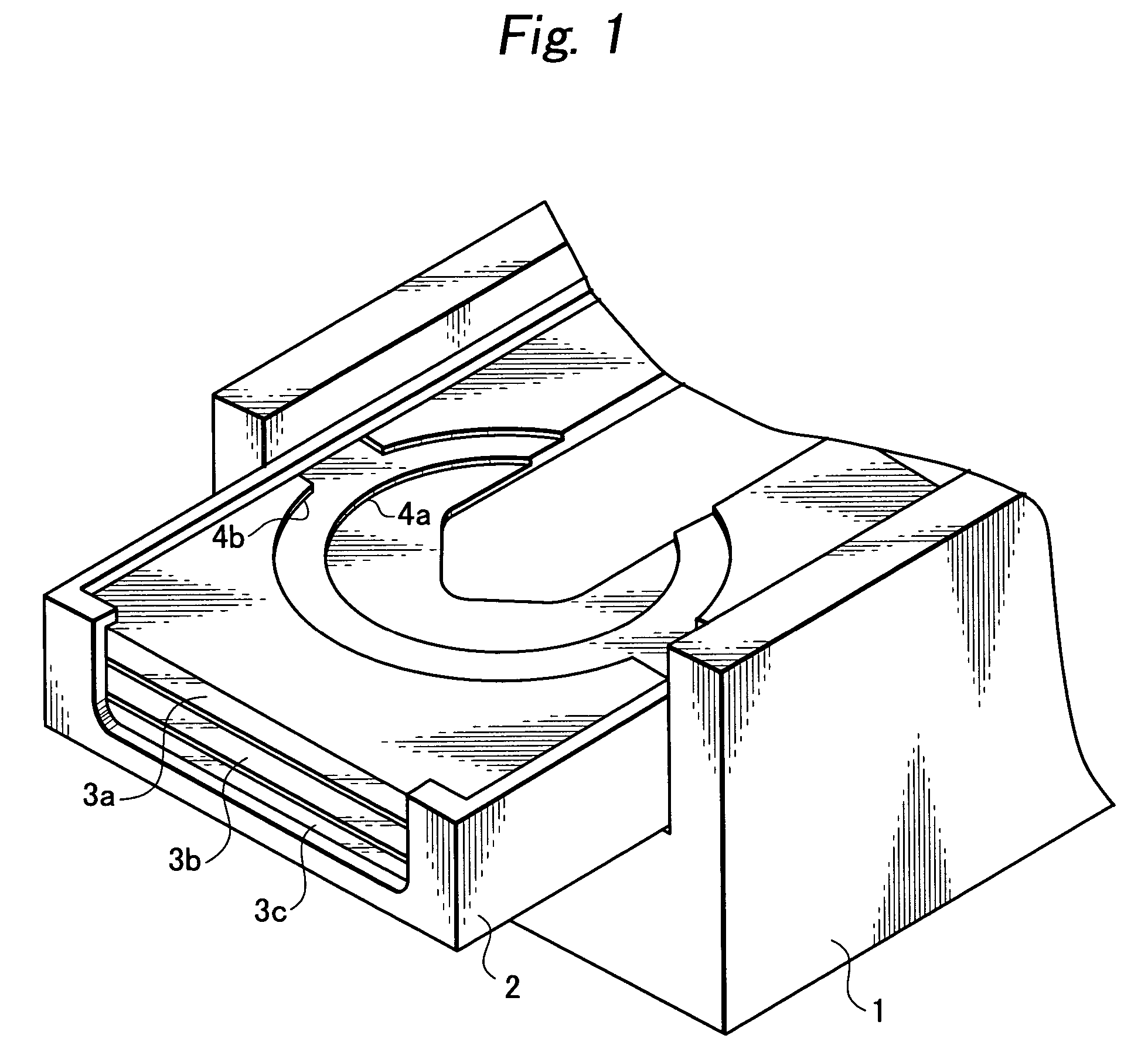
[0039]Hereinafter, an embodiment according to the invention is described in detail according to drawings. FIG. 1 shows a condition where the main tray is drawn out and located between the disc exchange position (disc removal position) and the disc waiting position. In the figure, numeral 1 shows a body frame, numeral 2 is a main tray, and numeral 3 shows sub-tray respectively, and three sub-trays 3a, 3b, and 3c are piled and accommodated in the main tray 2. In each of the sub-trays 3a, 3b, and 3c, concentric fringes 4a, 4b are formed with difference in level so that two discs, small and large may be carried on.

[0040]When a disc is carried on each of the sub-trays 3a, 3b, and 3c, or when the disc is removed, a sub-tray located at an upper side is locked and remained in the body frame 1, and the main tray 2 is conveyed to the disc exchange position together with a sub-tray located at a lower side. In this way, the sub-trays 3a, 3b, and 3c are accommodated in the main tray 2, and carri...


PUM

PropertyMeasurementUnit
heightaaaaaaaaaa
transmissionaaaaaaaaaa
poweraaaaaaaaaa

Abstract

To achieve a disc device with a disc changer in which number of motors is reduced, and a quiet and stable switching operation, accurate positioning of a sub-tray, smooth clamp and release of a disc are possible, only a first motor for driving a main tray and a second motor for driving the sub-tray are used as driving sources, and a gear switching mechanism is provided, in which driving channels of the first and second motors can be disconnected. The gear switching mechanism comprises a first cam gear having first and second cam grooves formed therein and rotationally driven by the first motor; a clutch lever installed in a back-and-forth swingable manner around a pivot fixed to a body frame and a back edge fitted slidably into the first cam groove in the first cam gear; a second cam gear having a cam groove formed therein and connected to a traverse-unit moving unit via the cam groove; and a clutch gear pivotally supported by a front edge of the clutch lever and capable of switching of connection to a channel including a transmission gear engaging with a sub-tray rack for conveying the sub-tray to the playback position, or to a channel including the second cam gear and transmission gears connected to the second motor.

Description

BACKGROUND OF THE INVENTION[0001]1. Field of the Invention[0002]The present invention relates to a disc device with a disc changer that accommodates a number of optical-disc storage media such as CD or DVD and automatically performs recording or playback of selected one storage medium, especially the disc device being a tray-type disc device with a disc changer having a number of trays that carries the storage media thereon and conveys the media.[0003]2. Related Art[0004]It is necessary in such disc device with the disc changer to accommodate a number of discs and select them for recording and playback, in addition, exchange the selected disc, therefore excessive, many operations including selection, positioning, and conveyance of a sub-tray, selection of a disc, and power switching are necessary, and necessarily additional motors are required as driving sources. On the other hand, a power switching mechanism, in which each operation may be selected and performed smoothly and accura...

Claims


Application Information

Patent Timeline
Patent Type & Authority Patents(United States)
IPC IPC(8): G11B17/04G11B33/02G11B17/22
CPCG11B17/225
Inventor SAKANO, KENJINISHIDE, MASAHIKOMOROISHI, MASAHIDE
Owner ORION ELECTRIC CO LTD
Why Eureka
Try Eureka