Disk cartridge

a technology of disk drives and cartridges, applied in the field of disk cartridges, can solve the problems of reducing restricting the design of the disk drive apparatus, and achieve the effects of increasing the degree of freedom of arrangement positions, increasing the degree of freedom of design of the disk drive apparatus, and increasing the degree of freedom of design

Inactive Publication Date: 2007-01-02
SONY CORP
View PDF50 Cites 12 Cited by
  • Summary
  • Abstract
  • Description
  • Claims
  • Application Information

AI Technical Summary

Benefits of technology

[0011]Accordingly, a disk cartridge according to the present invention aims to overcome the above-mentioned problems to increase the degree of freedom of the design of a disk cartridge and the positioning accuracy thereof.
[0014]Moreover, the use of at least two positioning portions among the first positioning portion, the second positioning portion, the third positioning portion, and the fourth positioning portion for the positioning the disk cartridge to the disk drive apparatus increases the degree of freedom of the arrangement positions of the positioning portions to be provided in the disk drive apparatus, and enables the increase of the degree of freedom of designing the disk drive apparatus. Moreover, the increase of the degree of freedom of designing makes it possible to simplify the mechanism of the disk drive apparatus, and to miniaturize the disk drive apparatus.
[0015]Moreover, because the first positioning portion and the second positioning portion are formed at the same position in the X direction, the third positioning portion and the fourth positioning portion are formed at the same position in the X direction, the first positioning portion and the third positioning portion are formed at the same position in the Y direction, and the second positioning portion and the fourth positioning portion are formed at the same position in the Y direction, there is no possibilities that any positional displacements are caused between the first positioning portion and the second positioning portion, and between the third positioning portion and the fourth positioning portion owing to dimensional tolerances in the X direction, and there is no possibilities that any positional displacements are caused between the first positioning portion and the third positioning portion, and between the second positioning portion and the fourth positioning portion owing to dimensional tolerances in the Y direction. Consequently, the positioning accuracy of the disk cartridge can be increased.
[0016]According to a second aspect of the present invention, the first positioning portion and the third positioning portion are positioned on the inserting direction side to the second positioning portion and the fourth positioning portion, and the first positioning portion and the third positioning portion are opened to at least the inserting direction side. The first positioning portion or the third positioning portion is used as the positioning of the disk cartridge to the disk drive apparatus when the disk cartridge is inserted through the insertion opening. Consequently, the positioning of the disk cartridge is performed in a predetermined direction when the disk cartridge is inserted from the insertion opening. Hence, it is difficult for the opening edge of the second positioning portion or the fourth positioning portion of the disk cartridge to be contacted with the positioning portions of the disk drive apparatus, and planing or the like between them owing to the contact can be prevented.
[0017]According to a third aspect of the present invention, the four positioning portions are opened to the same direction as the opening direction of the opening portion of the shell, and the positioning of the disk cartridge to the disk drive apparatus is performed at the time of a movement of the disk cartridge toward the opening direction of the opening portion. Consequently, the positioning of the disk cartridge to the disk drive apparatus can be performed at the same time as the insertion of the disk table into the opening portion, and the operation of the disk drive apparatus can be made to be more efficient and faster.

Problems solved by technology

As described above, in the conventional disk cartridge, the positioning relative to the disk drive apparatus is performed by means of the predetermined two positioning holes, and there is only one arrangement of the positioning pins to be formed in the disk drive apparatus, and consequently there is a problem that the designing of the disk drive apparatus is restricted to decrease the degree of freedom of the design thereof.

Method used


Image

  • Disk cartridge
  • Disk cartridge
  • Disk cartridge

Examples


Embodiment Construction

[0049]Hereinafter, the attached drawings will be referred to while the preferred embodiment of a disk cartridge according to the present invention is described.

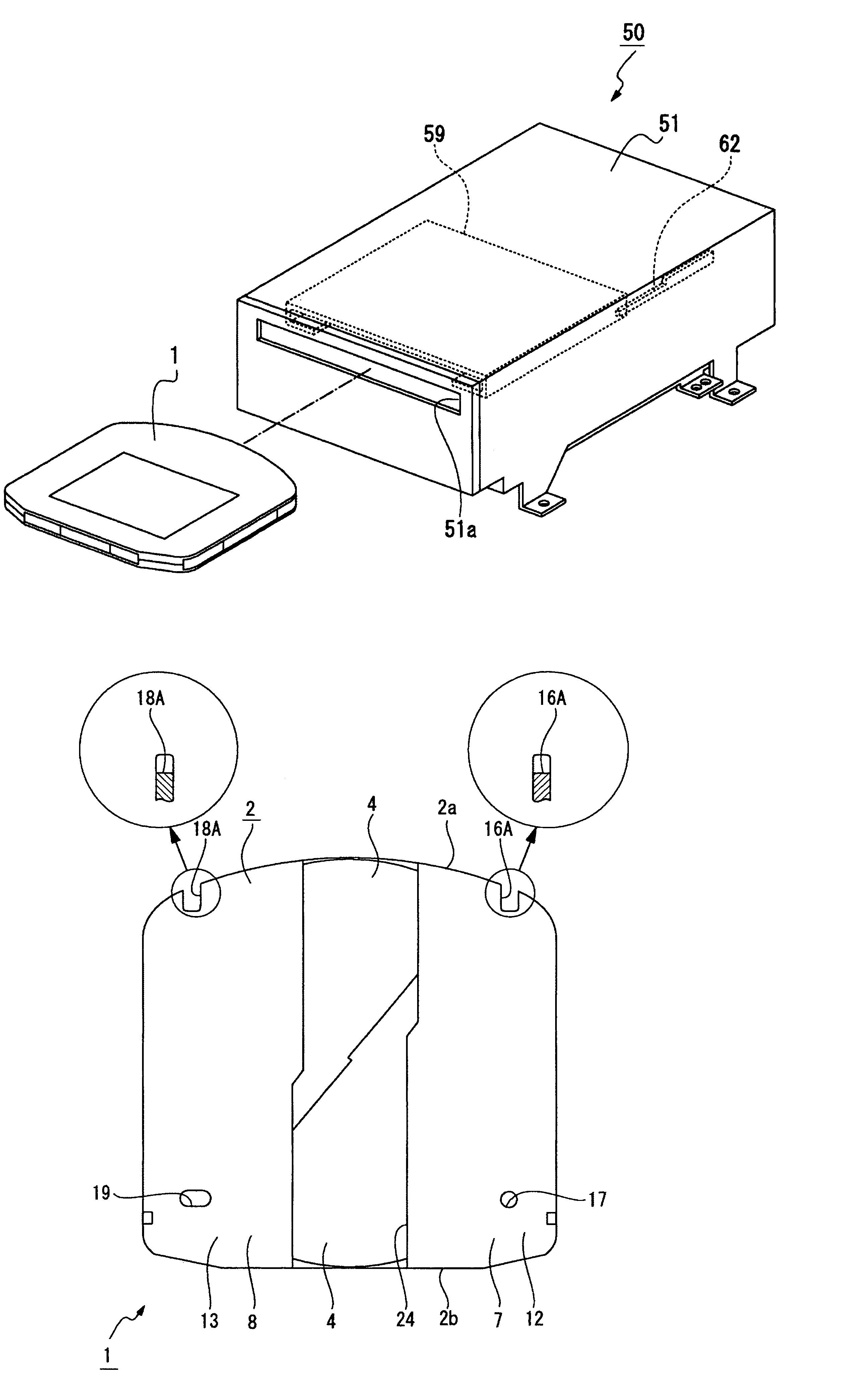
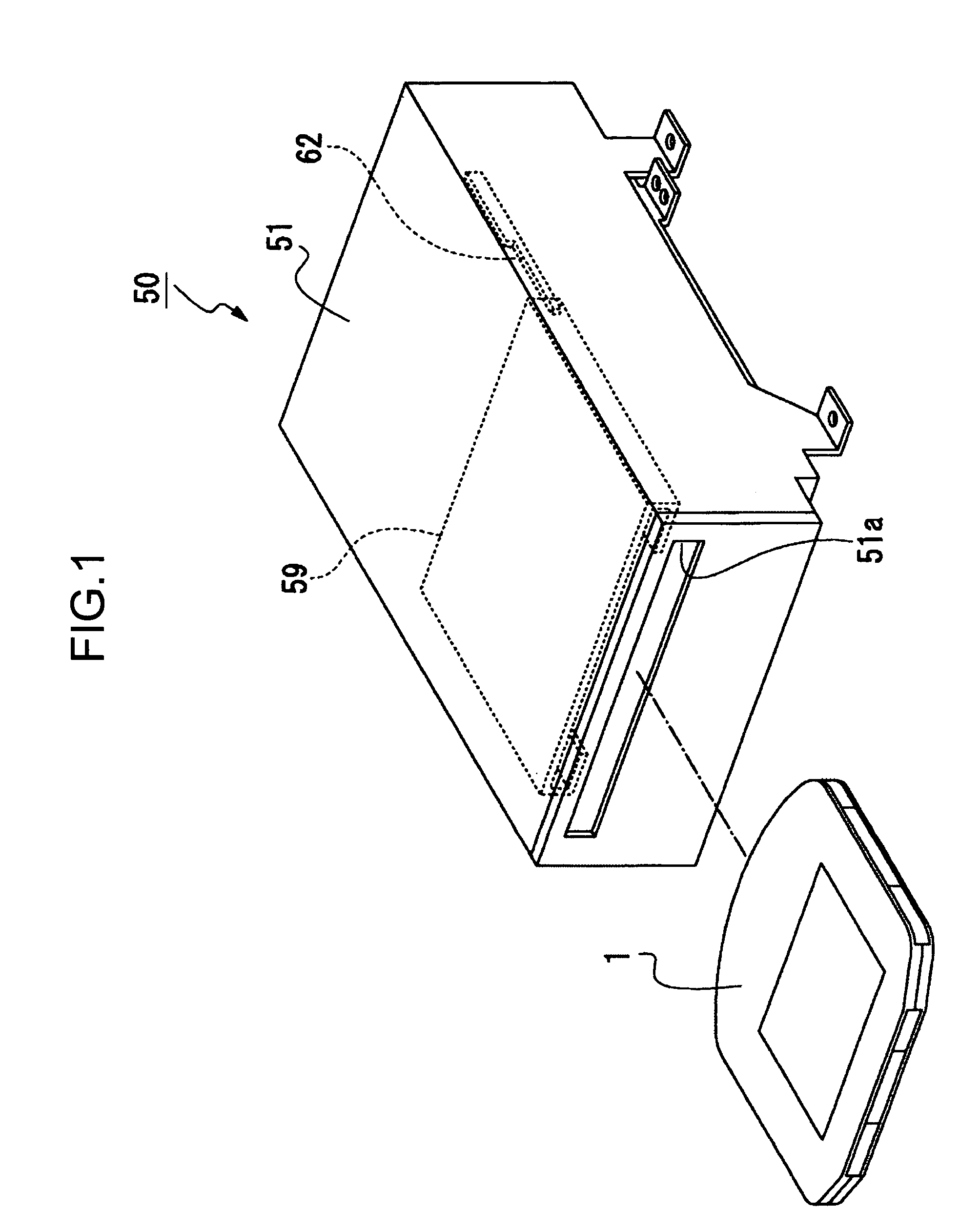
[0050]First, a disk drive apparatus in which the disk cartridge 1 is inserted and used will be described (see FIGS. 1 to 7). A disk drive apparatus 50 is composed of an outer casing 51, in which each of predetermined portions is arranged (see FIG. 1). On a front surface of the outer casing 51, an insertion opening 51a extended in a lateral direction is formed. The insertion opening 51a functions not only as an inserting portion through which the disk cartridge 1 is inserted in the outer casing 51, but also as an ejection portion, through which the disk cartridge 1 is ejected from the outer casing 51.

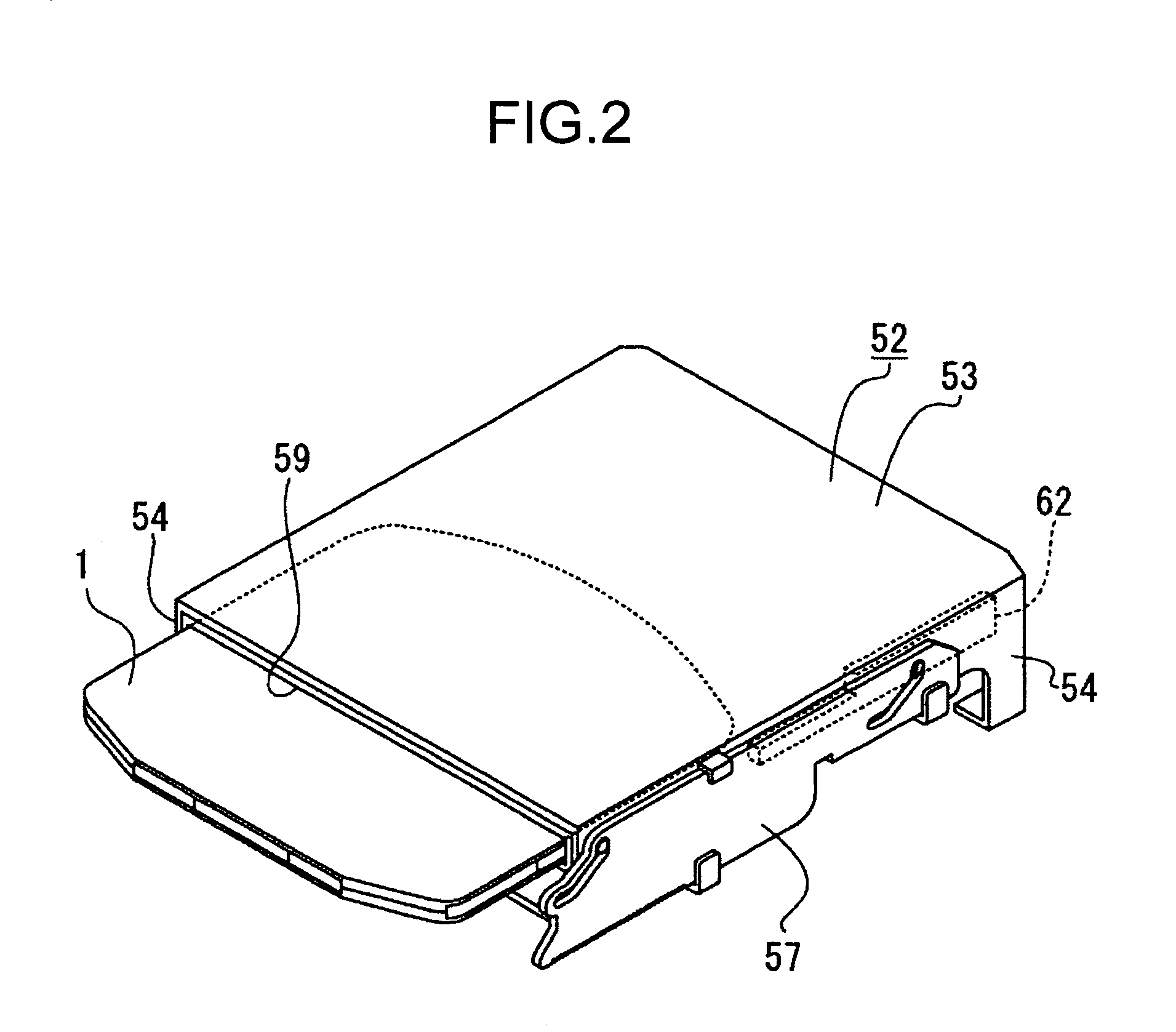
[0051]In the outer casing 51, a fixed frame 52 is arranged. As shown in FIG. 2, the fixed frame 52 includes a top plate portion 53 and side plate portions 54 both provided perpendicularly downward from side edges on both the sides...


PUM

PropertyMeasurementUnit
degree of freedomaaaaaaaaaa
thicknessaaaaaaaaaa
degree of freedomaaaaaaaaaa

Abstract

Four positioning holes or grooves of the first to the fourth positioning portions are formed on a shell as positioning portions to a disk drive apparatus. When two directions perpendicular to the thickness direction of a disk-shaped recording medium are designated as an X direction and a Y direction, the first and the second positioning portions are formed at the same position in the X direction, and the third and the fourth positioning portions are formed at the same position in the X direction, and further the first and the third positioning portions are formed at the same position in the Y direction, and still further the second and the fourth positioning portions are formed at the same position in the Y direction. When the disk cartridge is located to the disk drive apparatus at the insertion of the disk cartridge from an insertion opening, at least two of the four positioning portions are used.

Description

CROSS REFERENCE TO RELATED APPLICATION[0001]This application claims priority from Japanese Priority Document No. 2003-107377, filed on Apr. 11, 2003 with the Japanese Patent Office, which document is hereby incorporated by reference.BACKGROUND OF THE INVENTION[0002]1. Field of the Invention[0003]The present invention generally relates to a disk cartridge, and more particularly to a technology for increasing the degree of freedom in the design of a disk drive apparatus and the positioning accuracy of a disk cartridge to the disk drive apparatus by forming four positioning portions on a shell of the disk cartridge.[0004]2. Description of the Related Art[0005]There are disk cartridges, each including a shell and a disk-shaped recording medium rotatably housed in the shell, in which the shell is provided with an opening portion formed thereon for exposing a part of the disk-shaped recording medium to the outside (see, for example, Patent Document 1).[0006]When such disk cartridge is ins...

Claims


Application Information

Patent Timeline
Patent Type & Authority Patents(United States)
IPC IPC(8): G11B23/03
CPCG11B23/0316G11B23/0311G11B23/03
Inventor INOUE, NAOKISHIBAGAKI, SUSUMU
Owner SONY CORP
Why Eureka
Try Eureka