Optical transducer system having light emitting elements and light detecting elements both regulable in output characteristics

a technology of optical transducer and output characteristics, which is applied in the direction of optical radiation measurement, instruments, electrophonic musical instruments, etc., can solve the problems of detecting elements still introduced irregularities and age deterioration into detecting signals

Active Publication Date: 2007-01-09
YAMAHA CORP
View PDF11 Cites 18 Cited by
  • Summary
  • Abstract
  • Description
  • Claims
  • Application Information

AI Technical Summary

Benefits of technology

[0012]It is therefore an important object of the present invention to provide an optical transducer system, which produces detecting signals accurately expressing a physical quantity of moving objects.

Problems solved by technology

Although the light emitting elements were regulated through the current controlling circuit, the light detecting elements still introduced the irregularity due to the individuality thereof and aged deterioration into the detecting signals.

Method used


Image

  • Optical transducer system having light emitting elements and light detecting elements both regulable in output characteristics
  • Optical transducer system having light emitting elements and light detecting elements both regulable in output characteristics
  • Optical transducer system having light emitting elements and light detecting elements both regulable in output characteristics

Examples


first embodiment

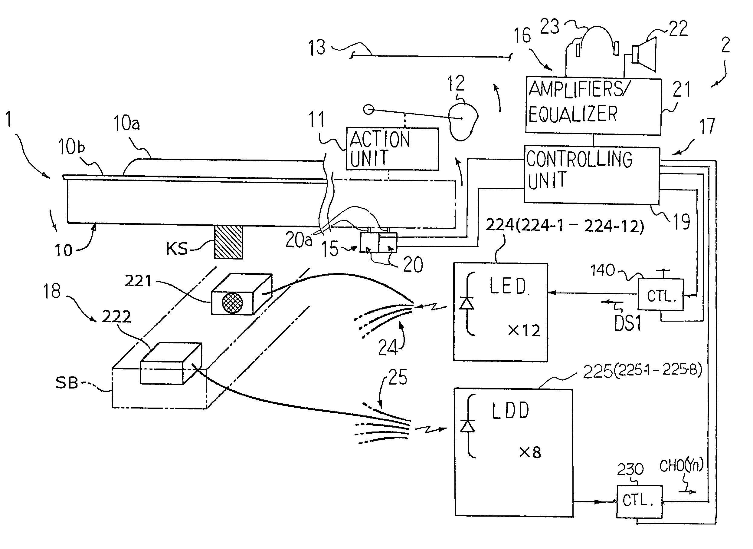
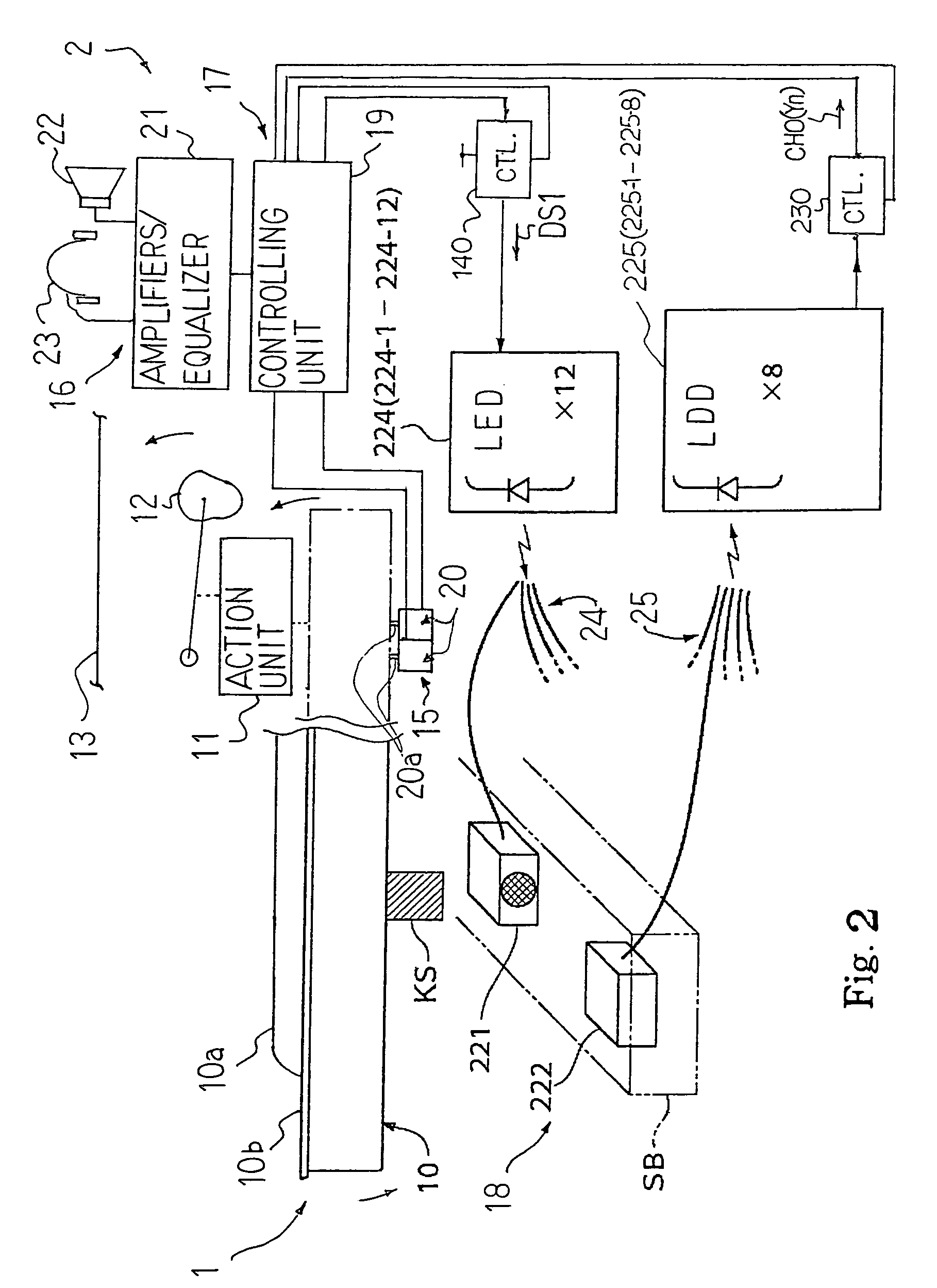
[0027]Referring to FIG. 2 of the drawings, an automatic player piano embodying the present invention largely comprises an acoustic piano 1 and an electronic system 2. A pianist fingers a piece of music on the acoustic piano 1, and acoustic piano tones are radiated from the acoustic piano 1. The electronic system 2 is installed in the acoustic piano 1, and gives two options to users. When a user instructs the electronic system 2 to perform a piece of music through the acoustic piano tones, the electronic system 2 produces the acoustic piano tones without any fingering of a human pianist. On the other hand, when the user takes the other option, the electronic system 2 produces electronic tones also without any fingering.

[0028]The acoustic piano 1 includes a keyboard 10, action units 11, hammers 12 and strings 13. Black keys 10a and white keys 10b are incorporated in the keyboard 10, and are laid on the well-known pattern. The black and white keys 10a, 10b are linked with the action un...

second embodiment

[0081]FIG. 8 shows another method for optimizing the luminescence led(x) and bias level CHO(y). An automatic player piano implementing the second embodiment is similar to the automatic player piano described as the first embodiment. For this reason, description is focused on a computer program, which expresses the method, and component parts of the automatic player piano are hereinbelow labeled with references same as those designating the corresponding component parts of the above-described automatic player piano.

[0082]When the optical transducer system 18 is powered, the central processing unit 201 starts to initialize the system, and enters a subroutine program for the optimization during the initialization. The central processing unit 201 firstly changes the luminescent control signal CL1 to the bit pattern indicative of the minimum luminescence led(3) and the potential control signal CL3 to the bit pattern indicative of the maximum bias level CHO(0) as by step S701. The lumines...

third embodiment

[0093]FIG. 10 shows another automatic player piano embodying the present invention. The automatic player piano embodying the present invention largely comprises an acoustic piano 1A and an electronic system 2A. The acoustic piano 1A is same as the acoustic piano 1, and component parts are labeled with references designating the corresponding parts of the acoustic piano 1A without detailed description. The electronic system 2A is similar to the electronic system 2 except for an optical transducer system 18A. For this reason, the other system components are labeled with references designating the corresponding system components, and description is focused on the optical transducer system 18A.

[0094]The optical transducer system 18A is only different in system configuration from the optical transducer system 18 in that the current-to-light converters 224 are not assisted with any controller. Only the bias controllers 230-1 to 230-8 are respectively connected between the light-to-current...


PUM


Abstract

Keys, which are incorporated in an automatic player piano, are monitored with an optical transducer system. The optical transducer system includes sensor heads provided on both sides of the key trajectories, LEDs connected to predetermined sensor heads through optical fibers, LDDs connected to the other sensor heads through optical fibers and a controlling unit. A luminescence controller is connected to the LEDs for optimizing the luminescence, and bias controllers are respectively connected to the LDDs. The luminescence controller and bias controllers optimize the luminescence of emitted light and the bias level of electric signals so that the optical transducer system is free from the individuality of component parts and the deterioration.

Description

FIELD OF THE INVENTION[0001]This invention relates to an optical transducer system and, more particularly, to an optical transducer system for converting a physical quantity to an electric signal.DESCRIPTION OF THE RELATED ART[0002]An optical transducer is incorporated in a hybrid keyboard musical instrument such as, for example, an automatic player piano and a mute piano. A typical example of the prior art optical transducer is disclosed in Japanese Patent Application laid-open No. Hei 9-54584. The Japanese Patent Application laid-open is corresponding to Japanese Patent Application No. Hei 7-270322, which offered the Convention Priority right to U.S. Ser. No. 08 / 658,700. The U.S. Patent Application was patented, and U.S. Pat. No. 5,824,930 was assigned to the U.S. Patent Application.[0003]The priority optical transducer is installed in the acoustic piano, and includes twelve light emitting diodes, eight light detecting diodes, sensor heads, shutter plates and optical fibers. A shu...

Claims


Application Information

Patent Timeline
Patent Type & Authority Patents(United States)
IPC IPC(8): G01V8/10G01J1/28G01J1/34G10F1/02G10H1/34
CPCG10H1/344
Inventor URA, TOMOYUKISASAKI, TSUTOMUOHBA, YASUHIKOHASHIMOTO, MASAHISA
Owner YAMAHA CORP
Why Eureka
Try Eureka