LED package including a frame

a technology of led package and frame, which is applied in the direction of electrical equipment, semiconductor devices, semiconductor/solid-state device details, etc., can solve the problems of reducing the power of led light emission, reducing or losing the capability of light emission, and damage to the light-emitting chip, etc., to achieve simple structure, increase heat dissipation and lifetime, and improve the effect of heat dissipation efficiency

Active Publication Date: 2007-01-09
LITE ON IT TECH CORP
View PDF4 Cites 75 Cited by
  • Summary
  • Abstract
  • Description
  • Claims
  • Application Information

AI Technical Summary

Benefits of technology

[0008]The primary object of the present invention is to provide a power LED package module. The power LED package module includes a conductive pin and a support separated from each other in order to prevent heat conduction from communicating with electrical conduction as well as to avoid conducting heat from the conductive pin to the light-emitting chip. The power LED package module further includes a package body, and a chip heat-conducting support with a part exposed outside the package body to connect with a heat-dissipating element for increasing the efficiency of the heat dissipation and lifetime. The chip heat-conducting support also has the advantages of simpler structure and cheaper cost than the related art.

Problems solved by technology

The excessive temperature of the PN junctions reduces the power of the light emission of LEDs.
Therefore, the light-emitting chip bears a larger mechanical force and reduces or loses the capability of the light emission.
The high heat damages the light-emitting chip 12a and reduces the lifetime.
As is evident, the LED package structure of related art is structurally complex, so it increases costs.

Method used


Image

  • LED package including a frame
  • LED package including a frame
  • LED package including a frame

Examples


Embodiment Construction

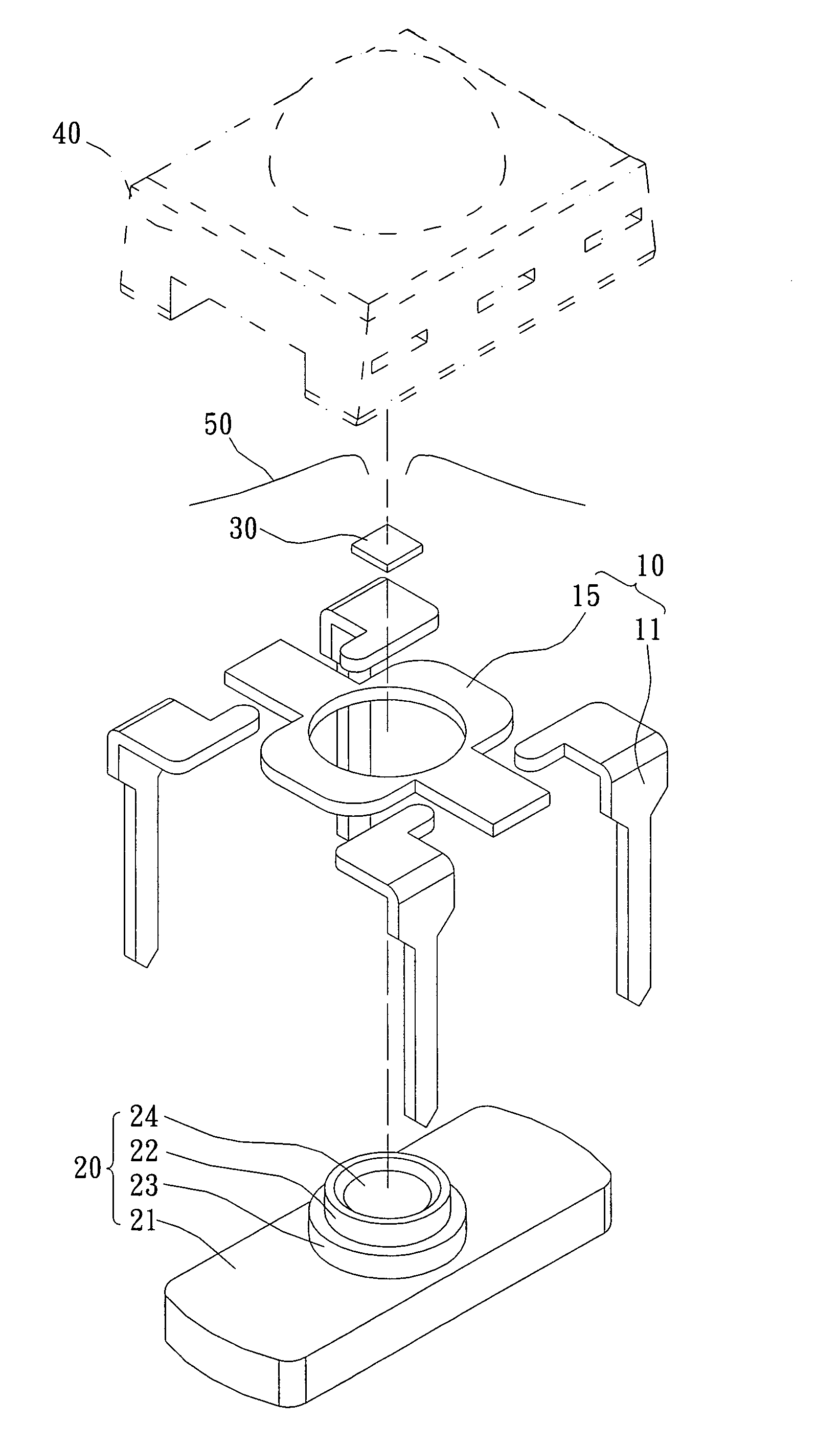
[0026]Referring to FIG. 3, the present invention provides a power LED package module. The power LED package module includes a frame 10, a chip heat-conducting support 20, a light-emitting chip 30 and a package body 40. The frame 10 has four conductive pins 11 and a support 15. The light-emitting chip 30 is arranged on the chip heat-conducting support 20. The chip heat-conducting support 20 connects with the support 15. The package body 40 is disposed on the four conductive pins 11, the support 15 and the chip heat-conducting support 20, in order to package the light-emitting chip 30 on the chip heat-conducting support 20 and expose a part of the chip heat-conducting support 20. Then, when the power LED package module electrically connects to a PCB, the exposure of the part of the chip heat-conducting support 20 contacts against the PCB or a heat-dissipating device for increasing the efficiency of heat dissipation. The four conductive pins 11 and the support 15 are separated from eac...


PUM


Abstract

A power LED package module includes a frame, a chip heat-conductive support, a light-emitting chip and a package body. The frame has a conductive pin, and a support separated from the conductive pin and connecting to the chip heat-conductive support. The light-emitting chip is arranged on the chip heat-conducting support and electrically connected to the conductive pin. The frame, the chip heat-conducting support and the light-emitting chip are packaged via the package body. The chip heat-conducting support is partially exposed out of the package body for connecting to a heat-dissipating element for increasing the efficiency of heat dissipation of the power LED package module. The power LED package module thus provides electrical conduction and heat conduction in a split manner.

Description

BACKGROUND OF THE INVENTION[0001]1. Field of the Invention[0002]The present invention relates to a power LED package module, and especially to a power LED package for increasing efficiency of heat dissipation and separating electrical conduction and heat conduction.[0003]2. Description of Related Art[0004]According to the manufacturing technology of LEDs and the increasing expansion of the application range of LEDs, it is necessary to increasingly raise the brightness of LEDs. The first method to achieve this goal is to increase the light-emitting efficiency of LEDs or photoelectrical exchange efficiency of LEDs. The second method is to increase the power of LEDs. The second method is a popular method in manufacturing. The temperature of the PN junctions is increasingly raised according to the increase of the input current in a light-emitting chip of LEDs. The excessive temperature of the PN junctions reduces the power of the light emission of LEDs. Moreover, the support of the ligh...

Claims


Application Information

Patent Timeline
Patent Type & Authority Patents(United States)
IPC IPC(8): H01L27/15H01L23/04H01L23/34H01L33/48H01L33/62H01L33/64
CPCH01L33/486H01L33/642H01L33/483H01L33/62H01L2224/48247H01L2224/48091H01L2924/00012H01L2924/00014
Inventor WU, YUNG-FU
Owner LITE ON IT TECH CORP
Why Eureka
Try Eureka