Regulating device for a motor

a technology of regulating device and motor, which is applied in the direction of motor/generator/converter stopper, dynamo-electric converter control, instruments, etc., can solve the problems of power loss produced during the operation of electronic switching devices, and the need for additional switching devices, so as to save operating costs

Inactive Publication Date: 2007-01-09
SIEMENS AG
View PDF24 Cites 12 Cited by
  • Summary
  • Abstract
  • Description
  • Claims
  • Application Information

AI Technical Summary

Benefits of technology

[0016]The communication module preferably has an interface to a bus system. The link to the interface to a bus system results in further advantages, such as that of central control and instrumentation. This results in flexibility in terms of the use of functions and procedures, coverage of a requirement for complex applications, savings in operating cost resulting from system intelligence and transparency with respect to the operating states, which can be implemented using visualization techniques.

Problems solved by technology

Switching devices of this type have been widely tested and been very well proven in practice, but can be used only to a limited extent in a direct encapsulated application, for example close to a motor, owing to their operating characteristics.
The problems in this case are firstly the power loss which is produced during operation of the electronic switching devices and is counteracted by complex cooling measures.
Secondly, owing to safety considerations, an additional switching device is often required, to carry out the task of disconnection via switching pieces in order to produce an air gap.

Method used


Image

  • Regulating device for a motor
  • Regulating device for a motor

Examples


Embodiment Construction

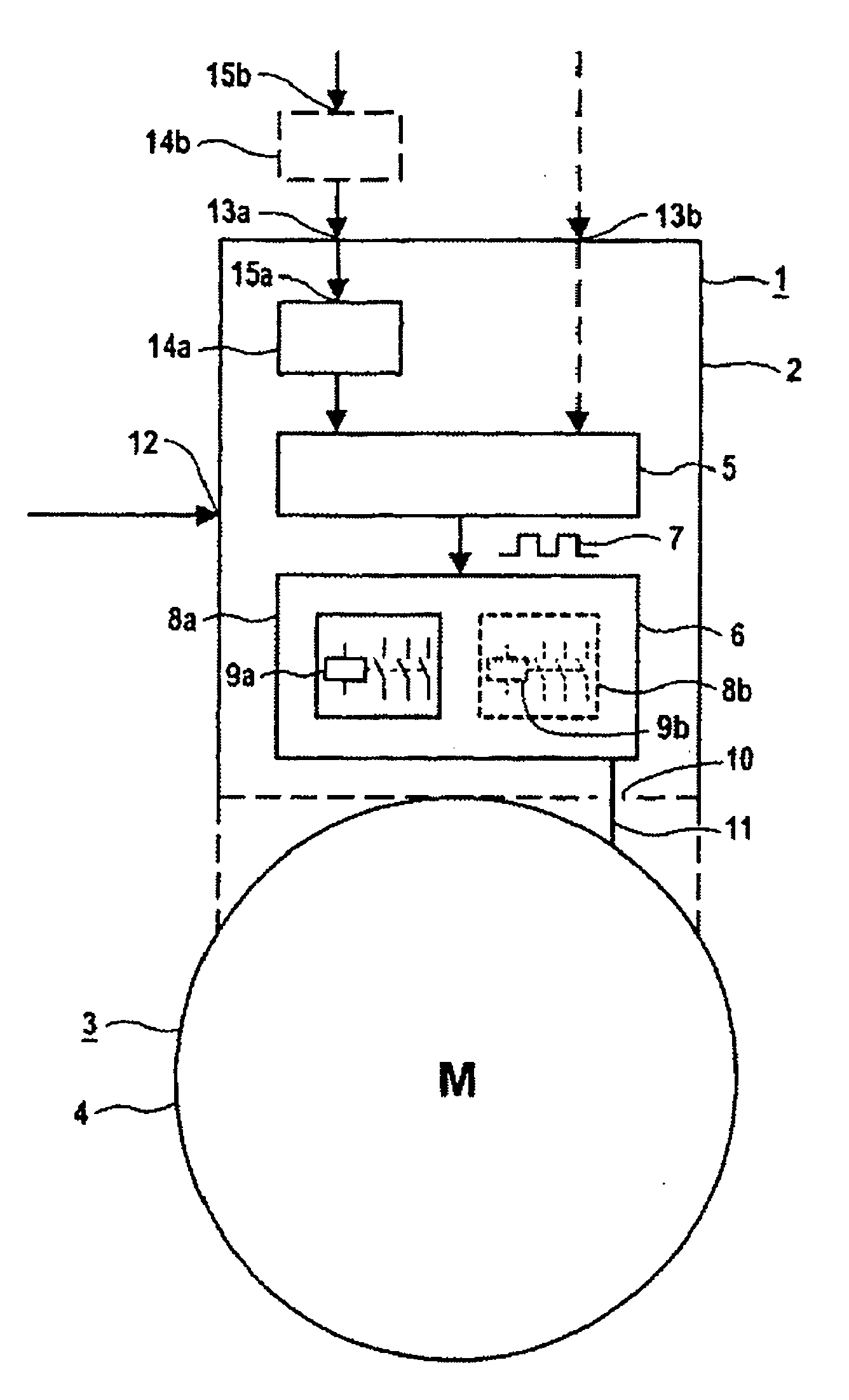
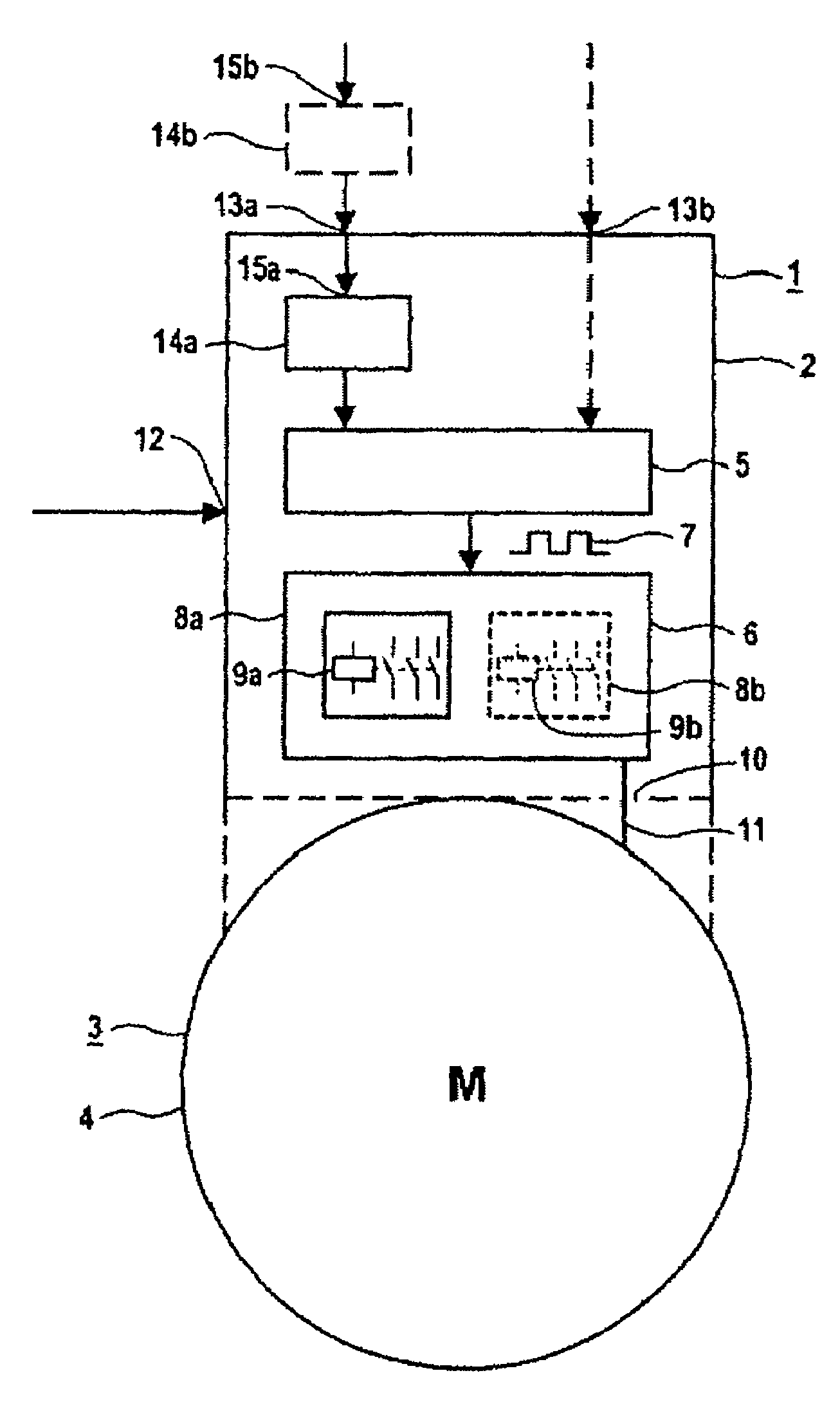
[0020]Design details will be described first of all, followed by functional and control details.

[0021]The control apparatus 1 has a housing 2 which can be matched to a motor housing 4 of a motor 3 which is surrounded by this motor housing 4, and can be matched to its contours. The housing 2 may in this case be in the form of a motor terminal box, complying with various ingress protection classes, as required. The arrangement of the control apparatus 1 on the motor housing 4 may be provided with attachment devices that are familiar from the prior art. The attachment may be provided in a force-fitting and / or interlocking manner.

[0022]In contrast to previous control apparatuses, also in the form of motor starters or of starters in the form of electromagnetic switching elements, no separate housing is any longer required for the embodiment of the housing 2 as a motor terminal box. There is no need for the previous complex connections between the control apparatus and the motor. The cont...


PUM


Abstract

The invention relates to a regulating device (1) for a motor, comprising a housing (2) which can be associated with said motor and in which a control unit (5) and an actuator (6) are arranged. Due to heat-related reasons, said device can only be used in an encapsulated manner, for example close to a motor. In order to solve this problem, the actuator (6) comprises an electromagnetic switching element (8a,8b) and the control signal (7) for the same is designed as a timing signal which is measured—taking into consideration at least one heat source inside or optionally outside the housing (2)—in such a way that the operating temperature of the electromagnetic switching element (8a,8b) is below an upper authorised limiting value.

Description

[0001]This application is the national phase under 35 U.S.C. § 371 of PCT International Application No. PCT / DE02 / 00452 which has an International filing date of Feb. 7, 2002, which designated the United States of America and which claims priority on German Patent Application number DE 101 08 548.6 filed Feb. 22, 2001, the entire contents of which are hereby incorporated herein by reference.FIELD OF THE INVENTION[0002]The invention generally relates to a control apparatus for a motor.BACKGROUND OF THE INVENTION[0003]A control apparatus is used in conjunction with further elements inter alia for starting, switching on and switching off equipment, such as a motor. The area of application of such control apparatuses extends, for example, from use in a controller for systems to use in machines.[0004]A control apparatus of a generic type with elements such as a control unit and a control element in the form of a switching device have been known for a long time in practice. Switching devic...

Claims


Application Information

Patent Timeline
Patent Type & Authority Patents(United States)
IPC IPC(8): H02P7/00H02K5/22H02K11/00H02K11/33H02P29/02
CPCH02P29/02H02K11/0073H02K5/225H02K11/33
Inventor HAUSELT, PETERKASER, JOSEFLEHMEIER, ANNEMARIEMEINKE, MARTINNIEDERMEIER, KARLNOTH, CHRISTOPHULRICH, JENSWUNSCHIK, ROMAN
Owner SIEMENS AG
Why Eureka
Try Eureka