Rotor thermal model for use in motor protection

a thermal model and motor protection technology, applied in emergency protective circuit arrangements, emergency protective arrangements responsive to undesired changes, electrical appliances, etc., can solve the problems of less than optimum protection performance, less than optimum protection for the motor, and true temperature overload appropria

Active Publication Date: 2007-01-09
SCHWEITZER ENGINEERING LABORATORIES
View PDF8 Cites 18 Cited by
  • Summary
  • Abstract
  • Description
  • Claims
  • Application Information

AI Technical Summary

Problems solved by technology

In the thermal model arrangement disclosed in the '784 patent, the run condition time-current curve did not match the time-current curve of the start condition, resulting in less than optimum protection for the motor, due to either the rotor or the starter being individually the limiting factor in the protection, instead of both having equal effect.
In such cases, a time constant must be determined and then added to the thermal protection cal

Method used


Image

  • Rotor thermal model for use in motor protection
  • Rotor thermal model for use in motor protection
  • Rotor thermal model for use in motor protection

Examples


Embodiment Construction

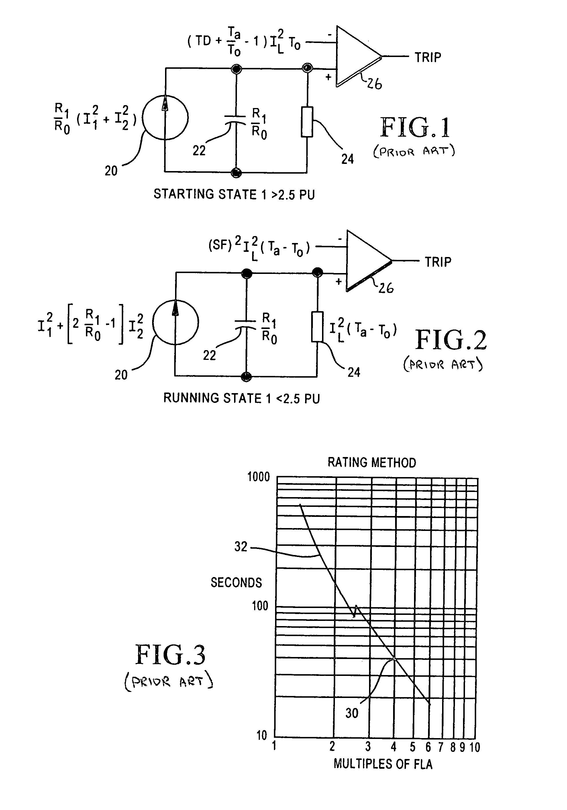
[0013]As indicated above, the use of start and run condition thermal models to provide protection for motors based on the actual heating and cooling of the motor during operation is known. The electrical analog representations of the start and run conditions are briefly discussed above and discussed in some detail in the '784 patent, and are shown in FIGS. 1 and 2. Again, the start condition of the motor is when the measured current to the motor (I) is greater than 2.5 times the full load current, while the run condition of the motor is defined as when the measured current is less than 2.5 times the full load current. The full load current (“FLC”) value is supplied by the manufacturer.

[0014]The heating effect of the motor in FIGS. 1 and 2 is represented at 20, the thermal capacity at 22 and the cooling effect at 24 (zero for the start condition). The combined result is compared against a threshold value by comparator 26 and a trip decision is made.

[0015]Each of those thermal model h...


PUM


Abstract

The protective relay for an induction motor includes a first program function which establishes a first thermal threshold value for a start condition of the motor, using a start condition thermal model. The thermal condition of the motor is determined by measuring the motor's thermal response to stimulus. A comparator compares the start condition thermal representation with the first thermal threshold value and monitors whether the first thermal threshold value is exceeded by the start condition thermal representation. A second thermal threshold value is established for a run condition of the motor, including a selected time constant which results in the time-current curves of the start and run conditions being substantially continuous. A representation of the thermal condition of the motor is then developed in response to stimulus current. A comparator then compares the run condition thermal representation with the second thermal threshold value.

Description

TECHNICAL FIELD[0001]This invention relates generally to temperature protection for induction motors, and more specifically concerns a system using thermal models for the protection of motors.BACKGROUND OF THE INVENTION[0002]U.S. Pat. No. 5,436,784, owned by the assignee of the present invention, discloses the use of thermal models to determine when an overload condition has been reached relative to calculated temperatures in the motor. The contents of the '784 patent are hereby incorporated by reference. The thermal models include one model for a start condition of the motor, defined as when the measured rotor current is relatively high, specifically, greater than 2.5 times the full load rated motor current, and a second model for a run condition of the motor, i.e. when the motor is at rated speed, defined as when the rotor current is less than 2.5 times the maximum rated current.[0003]The thermal models are determined using values of full-load motor current, locked rotor current, ...

Claims


Application Information

Patent Timeline
IPC IPC(8): H02H7/08H02H6/00
CPCH02H6/00H02H7/0816
Inventor ZOCHOLL, STANLEY E.
Owner SCHWEITZER ENGINEERING LABORATORIES
Why Eureka
Try Eureka