Device and method for motion video encoding reducing image degradation in data transmission without deteriorating coding efficiency

a technology of motion video and coding efficiency, which is applied in the direction of color television with bandwidth reduction, signal generator with optical-mechanical scanning, television systems, etc., can solve the problems of increasing the probability of data discarding, increasing the probability of serious degradation in the next frame, and affecting the quality of subjective images, so as to achieve the effect of reducing image degradation without deteriorating coding efficiency

Inactive Publication Date: 2007-01-09
NEC CORP
View PDF7 Cites 31 Cited by
  • Summary
  • Abstract
  • Description
  • Claims
  • Application Information

AI Technical Summary

Benefits of technology

[0015]It is therefore the primary object of the present invention to provide a motion video encoding device and a motion video encoding method, by whi...

Problems solved by technology

As the probability of the error-caused degradation in a referred area of the transmitted frame increases, the probability of serious degradation in the next frame increases.
By such propagation of degradation through frames, subjective image quality is degraded considerably.
Therefore, if transmission error occurs at random, the probability of the data discard increases as the coded data gets far from the latest synchronization code pattern.
In the conventional motion video encoding device, the forced refresh is carried out with higher priority to blocks having high degradation power and high data loss probability, since the degree of image degradation gets higher if error occurs to such blocks...

Method used


Image

  • Device and method for motion video encoding reducing image degradation in data transmission without deteriorating coding efficiency
  • Device and method for motion video encoding reducing image degradation in data transmission without deteriorating coding efficiency
  • Device and method for motion video encoding reducing image degradation in data transmission without deteriorating coding efficiency

Examples


embodiment 1

[Embodiment 1]

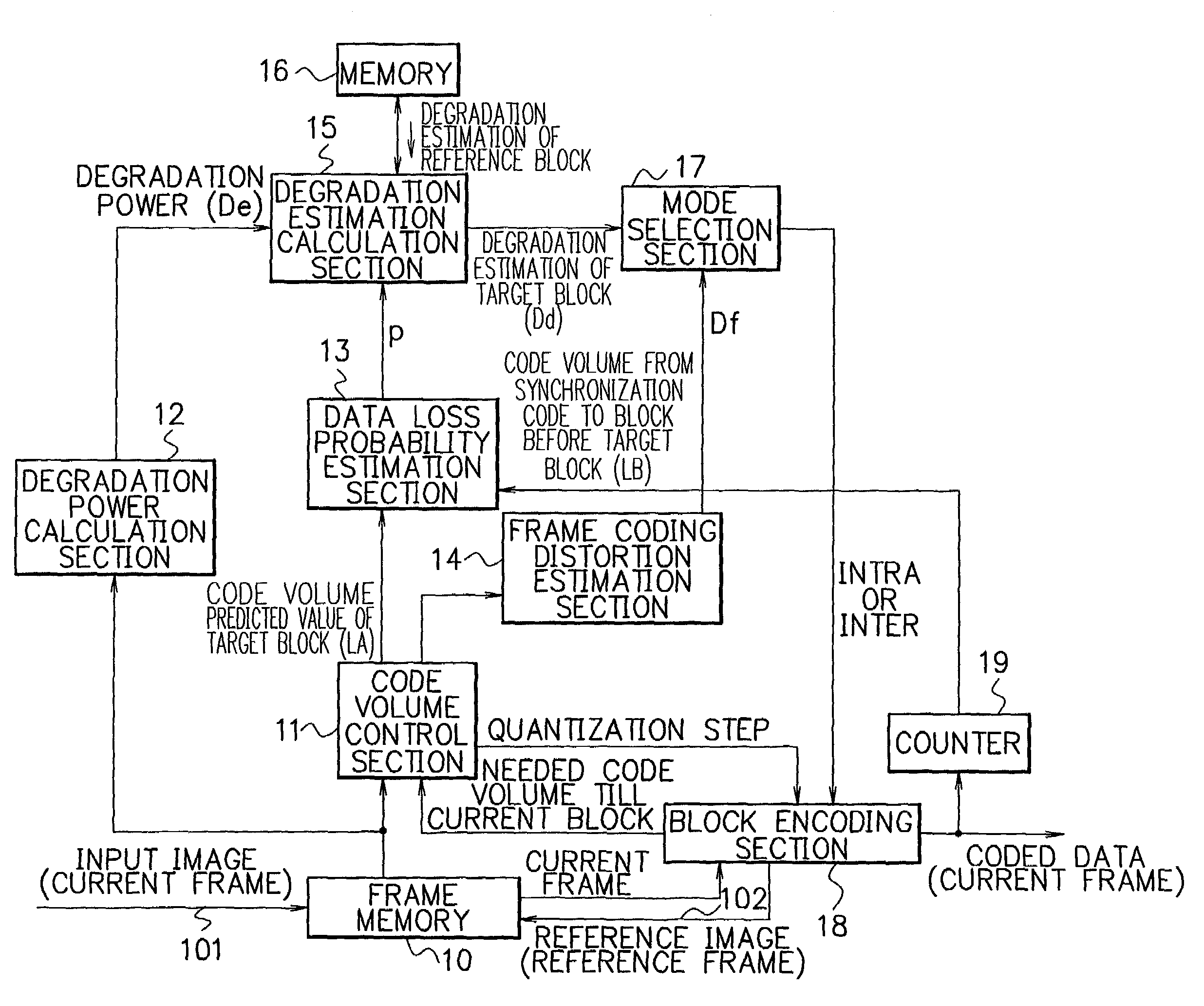
[0049]FIG. 3 is a block diagram showing an example of the composition of a motion video encoding device in accordance with a first embodiment of the present invention. The motion video encoding device of FIG. 3 includes a frame memory 10, a code volume control section 11, a degradation power calculation section 12, a data loss probability estimation section 13, a frame coding distortion estimation section 14, a degradation estimation calculation section 15, a memory 16, a mode selection section 17, a block encoding section 18, and a counter 19.

[0050]The components shown in FIG. 3 can be implemented by, for example, a microprocessor unit which is composed of a CPU (Central Processing Unit), ROM (Read Only Memory), RAM (Random Access Memory), etc., and appropriate software. Such software for realizing the operation of the motion video encoding device is stored in one or more record mediums and provided to the motion video encoding device so as to be loaded into the devic...

embodiment 2

[Embodiment 2]

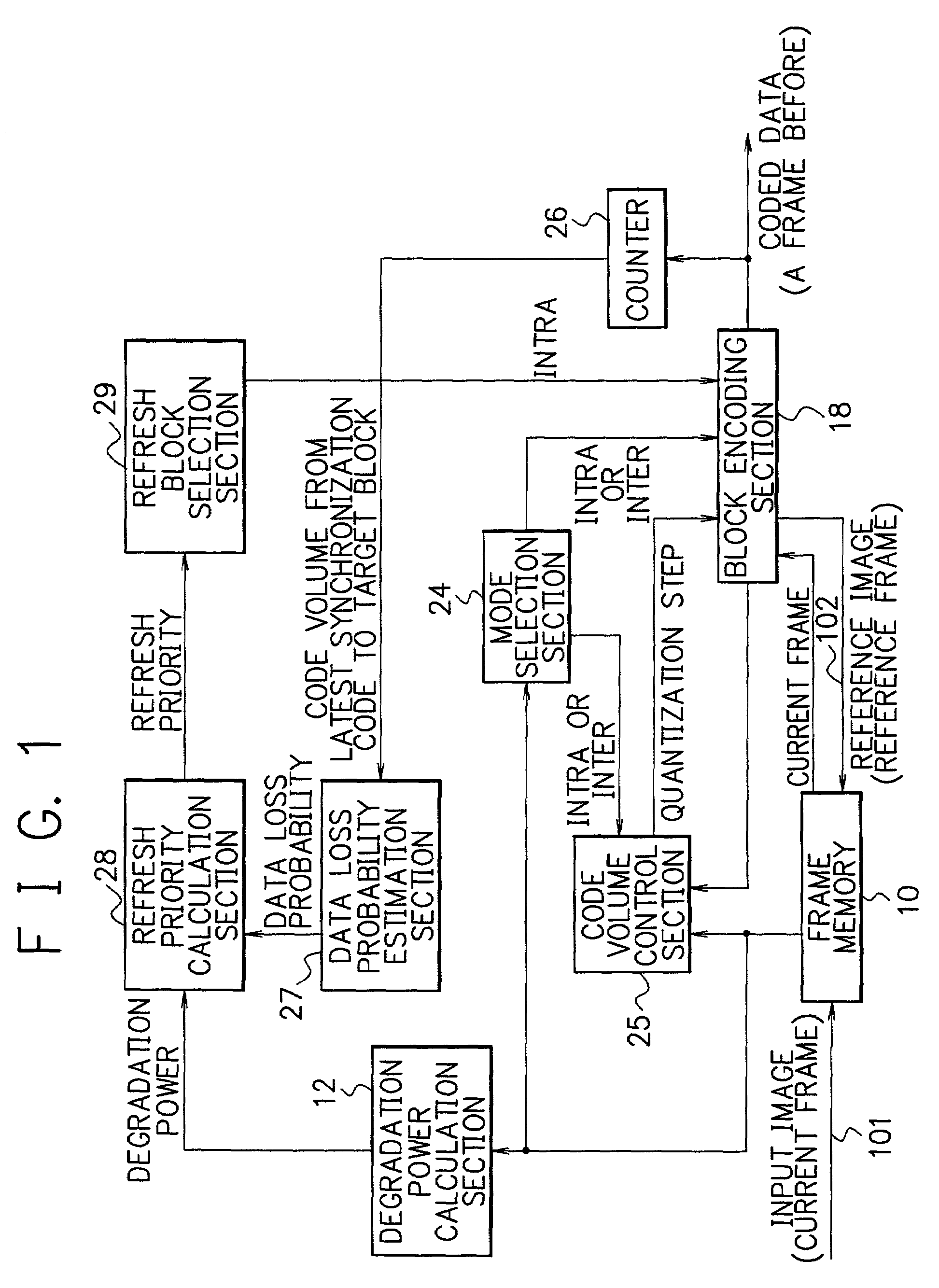
[0074]FIG. 6 is a block diagram showing an example of the composition of a motion video encoding device in accordance with a second embodiment of the present invention. The motion video encoding device of FIG. 6 further includes a block coding distortion estimation section 21, in comparison with the first embodiment of FIG. 3.

[0075]The mode selection section 20 shown in FIG. 6 operates a little differently from the mode selection section 17 of FIG. 3. The mode selection section 20 refers to block coding distortion Db which is calculated by the block coding distortion estimation section 21 in addition to the degradation estimation Dd of the target block calculated by the degradation estimation calculation section 23 and the frame coding distortion Df calculated by the frame coding distortion estimation section 14, and thereby selects an encoding mode from three encoding modes: the intra-frame encoding (INTRA); the inter-frame prediction encoding (INTER); and “skip” (SKI...


PUM


Abstract

A code volume control section refers to an input image and a reference image stored in a frame memory and thereby sets a quantization step for each block so that the volume of coded data generated for a frame will be a preset volume. A data loss probability estimation section estimates a data loss probability (the probability that data loss will occur to a target block due to transmission error) based on a code volume predicted value of the target block obtained by the code volume control section and the code volume from the latest synchronization code pattern to a block just before the target block. A degradation estimation calculation section calculates an estimate of degradation of the target block caused by errors based on image degradation power and the data loss probability. A mode selection section selects an optimum encoding mode for the target block based on the degradation estimate of the target block and an estimate of frame coding distortion. Forced refresh (intra-frame encoding of a block) is carried out properly and effectively, thereby image degradation is reduced without deteriorating coding efficiency.

Description

BACKGROUND OF THE INVENTION[0001]The present invention relates to a motion video encoding device and a motion video encoding method, and in particular, to a motion video encoding device and a motion video encoding method capable of encoding video signals so as to reduce the degradation of video data caused by errors when coded video signals (compressed video signals, for example) are transmitted via transmission lines of low circuit quality.DESCRIPTION OF THE RELATED ART[0002]Various encoding methods have been employed for motion video encoding devices. In order to encode and transmit each frame (each input image) of input video data, a conventional motion video encoding device adaptively makes a selection from intra-frame encoding (INTRA) and inter-frame prediction encoding (INTER) for each block (as a unit of encoding) and uses the selected encoding mode for encoding the block. The conventional motion video encoding device makes the encoding mode selection for each block based on ...

Claims


Application Information

Patent Timeline
IPC IPC(8): H04N7/12H04N19/50H04N19/107H04N19/126H04N19/14H04N19/149H04N19/166H04N19/176H04N19/196H04N19/423H04N19/503H04N19/59H04N19/65H04N19/86H04N19/89
CPCH04N19/176H04N19/15H04N19/89H04N19/124H04N19/107
Inventor KIMOTO, TAKAHIRO
Owner NEC CORP
Why Eureka
Try Eureka