Light fixture wireless access points
a wireless access point and light fixture technology, applied in data switching networks, frequency-division multiplex details, coupling device connections, etc., can solve the problems of reducing the capacity of wireless networks, affecting the appearance, and requiring electrical power for distributed access points
- Summary
- Abstract
- Description
- Claims
- Application Information
AI Technical Summary
Problems solved by technology
Method used
Image

Examples
second embodiment
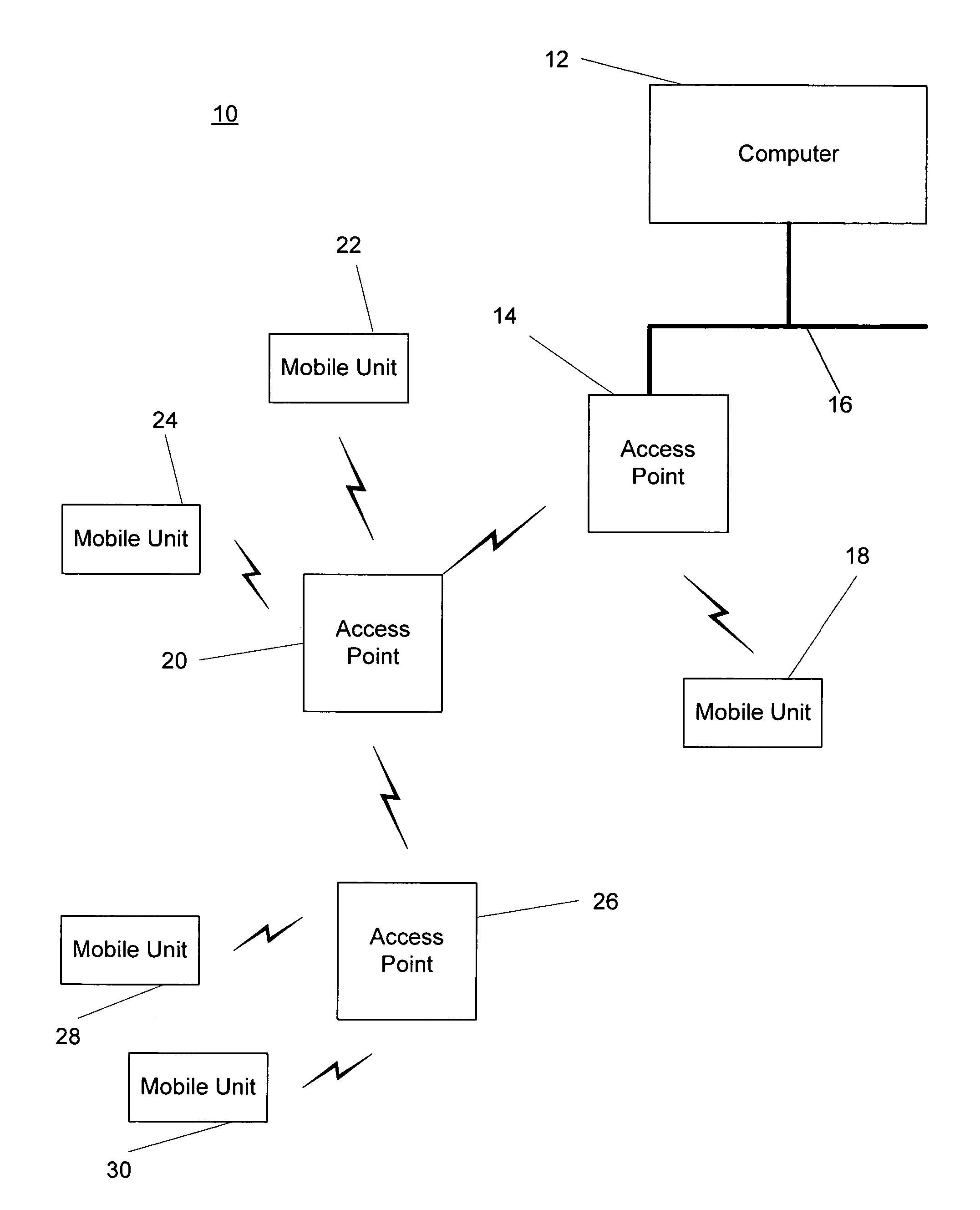
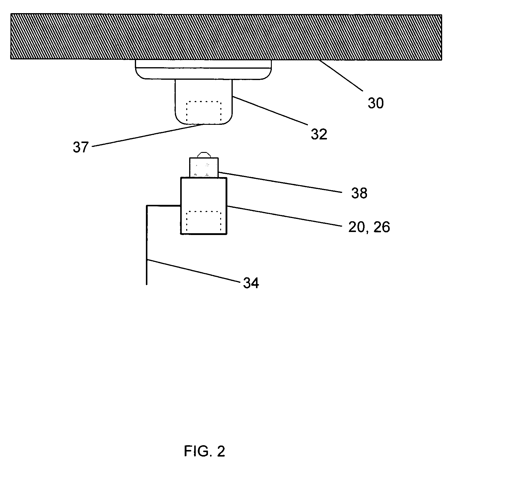
[0027]FIG. 3 shows the invention wherein a fluorescent fixture 40 is mounted on a ceiling 30 and includes sockets 46, 48 which are arranged for receiving a conventional fluorescent tube. In the arrangement of FIG. 3, a wireless communications device 42 is received in sockets 46 and 48 and includes an antenna 44 for providing wireless data communications. The wireless data communications device 42 has end connectors which are arranged to be received in sockets 46, 48 and a power supply which provides power to the wireless data communications device from the power supply to sockets 46 and 48.
third embodiment
[0028]In the arrangements of FIG. 2 and FIG. 3, the wireless data communications device replaces the illumination lamp in an illumination fixture in a facility. In most facilities there are provided sufficient illumination lamps for illuminating the space so that replacement of a few of the illumination lamps with the wireless data communications devices 2026 or 42 does not affect the overall illumination available within the workspace. FIG. 4 shows the invention wherein a wireless data communications device 50 having an antenna 44 is inserted into sockets 46, 48 of a fluorescent fixture 40 mounted on ceiling 30. The device 50 shown in FIG. 4 includes extension devices 5254 having further sockets 58 and 60 for receiving a conventional fluorescent tube 62 which will replace the fluorescent tube that was displaced when the wireless communications device 50 is inserted into the sockets 4648 of fixture 40. After insertion of the device 50 into the socket of the fluorescent fixture 40 an...
fourth embodiment
[0033]FIGS. 7 and 8 illustrate the invention wherein a fluorescent tube fixture 90, which is arranged to receive four 48-inch fluorescent tubes is mounted on ceiling 30. Fixture 90 includes sockets 92, 94, 96 and 98 which are arranged to receive two 48-inch fluorescent tubes. Fluorescent tube 100 is inserted between sockets 98 and 96 in a conventional manner. Wireless communications device in housing 102 is inserted into socket 94 and includes its own socket 104 which is arranged to receive a two 24-inch fluorescent tube 108 which is connected between socket 92 and socket 104 on wireless communications device 102. Socket 104 may be arranged with an adhesive surface to secure it to fixture 90. Alternatively, a threaded screw may be used to attach socket 104 firmly to fixture 90. Antenna 106 is provided extending from the housing device 102.
PUM
 Abstract
Description
Claims
Application Information
 - R&D
- Intellectual Property
- Life Sciences
- Materials
- Tech Scout
- Unparalleled Data Quality
- Higher Quality Content
- 60% Fewer Hallucinations
Browse by: Latest US Patents, China's latest patents, Technical Efficacy Thesaurus, Application Domain, Technology Topic, Popular Technical Reports.
© 2025 PatSnap. All rights reserved.Legal|Privacy policy|Modern Slavery Act Transparency Statement|Sitemap|About US| Contact US: help@patsnap.com