Method and apparatus for adaptive coordinated distribution of materials in railway maintenance and other applications

a technology for railway maintenance and other applications, applied in the direction of electric digital data processing, railway tracks, instruments, etc., can solve the problems of not being able to distribute the right number of ties, not being able to meet the needs of the equipment used to do tagging, not being able to mark the crew or the data capture or acquisition crew,

Active Publication Date: 2007-01-09
BRANDT ROAD RAIL CORP
View PDF3 Cites 9 Cited by
  • Summary
  • Abstract
  • Description
  • Claims
  • Application Information

AI Technical Summary

Benefits of technology

[0014]It is the object of the present invention to provide a method and apparatus for the adaptive distribution of random quantities of railroad ties at randomly spaced locations along a railroad right of way with a minimum of labour or cost.
[0015]It is a further object of the present invention to provide a method or apparatus by which these variable quantities of replacement railroad ties can be placed at non-standard or calculated locations where they are optimally located in relation to their eventual use in maintenance or replacement tasks.
[0016]It is the further object of the present invention to provide a method and apparatus for the adaptive distribution of railroad ties in railway maintenance applications which will allow for the marking or acquisition of the use location data with respect to these ties, to take place in a separate site inspection pass in advance of the equipment for distributing or replacing the railroad ties.
[0043]A central computer could be used to house all of the use location co-ordinates captured by the one or more use location capture modules of the method of the present invention. Basically, the use location capture modules could upload to the memory of a central computer, and more specifically into a location database stored therein, the use location co-ordinates which had been captured by use of the use location capture module(s) and then subsequently those use location co-ordinates could be used by the central computer, or more directly by a drop location detection module on a tie distribution machine, to properly calculate or locate drop locations and assist operators of the tie distribution equipment in the distribution of appropriate numbers of replacement ties or other materials at each such location.
[0049]The tie distribution equipment or machinery itself may be further equipped with a load cell or some other method of counting the ties which have actually been distributed, in order to provide comparative data to the operator of the machine and / or provide effectively a method of counting the ties which have been distributed for comparison to the required numbers.
[0050]It is also contemplated that either a slave display or a more elaborate secondary drop location detection module could be used in the power unit or locomotive of the train or equipment used to distribute the replacement ties and, effectively, what the slave display or the secondary drop location detection module would do would be to identify to the operator of the locomotive, who would in all likelihood be a second operator from that of the distribution equipment, when the distribution equipment was properly located at the co-ordinates of a drop location so that the train could be stopped in the appropriate place for the operator of the actual distribution equipment to drop the required number of ties. Either the use of a simple secondary display slaved to the primary marking module used in the distribution equipment could be contemplated, or a separate GPS enabled secondary drop location detection module which would either, based on communication with the primary drop location detection module or alternatively by virtue of some manual setting, apply the appropriate distance offset to the co-ordinates in question could also be used to properly locate the train in relation to the distribution equipment at the drop locations.

Problems solved by technology

This is not optimal in terms of distributing the right number of ties in a situation either where only a very few ties are required or where a large number that is not a multiple of the number in the batches is required.
One of the other limitations of the prior art, even where GPS has been used in the past to effectively tag the drop zones for banded quantities of railroad ties is that the equipment used to do the tagging has also been required to be physically present at the dropping of the material.
One of the limitations to this, of course, is that the marking crew or the data capture or acquisition crew who are marking the drop locations for their predetermined numbers of ties is required to only work as fast as the speed of the actual distribution train following along behind.
This is a significant time and cost problem since the data capture crew may, in all likelihood, be able to work fairly quickly and may be able to effectively travel over an entire railroad and accomplish their data capture function or tie marking function in the same amount of time which is taken by the tie replacement crew or the distribution crew to do a much lesser number of miles or kilometres of the overall maintenance requirement.

Method used


Image

  • Method and apparatus for adaptive coordinated distribution of materials in railway maintenance and other applications
  • Method and apparatus for adaptive coordinated distribution of materials in railway maintenance and other applications
  • Method and apparatus for adaptive coordinated distribution of materials in railway maintenance and other applications

Examples


Embodiment Construction

[0063]As required, detailed embodiments of the present invention are disclosed herein; however, is to be understood that the disclosed embodiments are merely exemplary of the invention, which may be embodied in various forms. Therefore, specific structural and functional details disclosed herein are not to be interpreted as limiting, but merely as a basis for the claims and as a representative basis for teaching one skilled in the art to variously employ the present invention in virtually any appropriately detailed structure or method.

[0064]Prior Art:

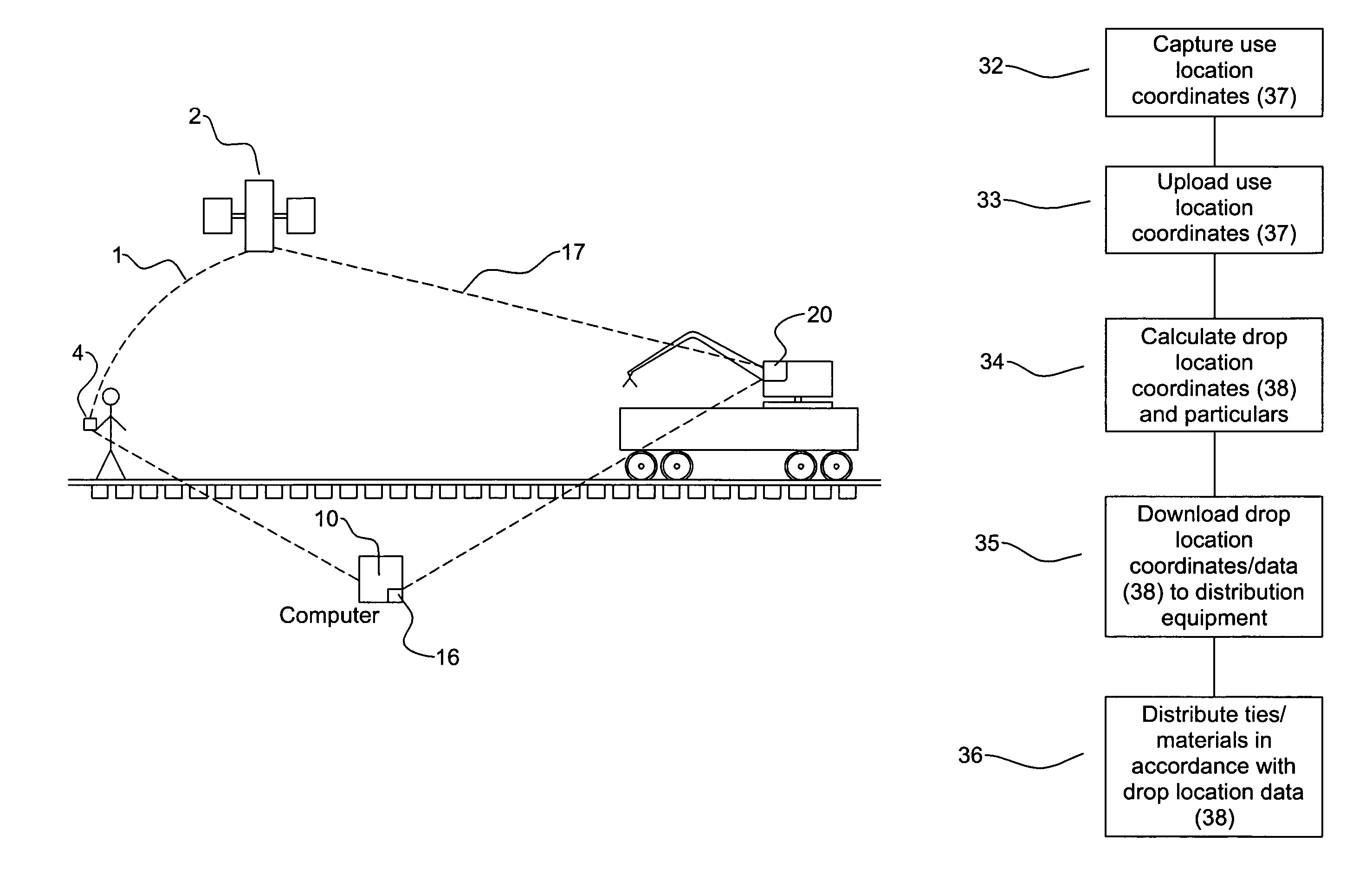
[0065]The method which has been used in the prior art in terms of replacement of ties constitutes a three-pass approach. Firstly, a marking crew or a sighting crew comes along the track and marks particular railroad ties which are to be replaced—typically with a splash of paint or the like. In a second pass, another crew comes along the track behind them and, using the marks that the marking crew has generated, drops the appropriate num...


PUM


Abstract

A method of distributing railroad ties or other materials in variable quantities at randomly spaced intervals. GPS coordinates are recorded for individual use locations where ties or materials are required. From the coordinates of these use locations, drop locations are selected at which materials can be conveniently dropped for subsequent use or installation. Capture of the use location coordinates is done by separate equipment from the distribution equipment, so that the data capture and distribution crews can work at their own efficiencies. The apparatus can be built into new railroad equipment or the like, or can also be manufactured in such a fashion as it can be retrofit. Computer software for the optimization and location of the drop locations is also disclosed.

Description

[0001]This invention relates generally to railway maintenance logistics, and more particularly relates to a GPS-based system for use in the distribution of railroad ties or similar materials along railroad tracks in railroad maintenance applications.BACKGROUND OF THE INVENTION[0002]Railroads in North America typically consist of a network of railroad tracks. Each of these railroad tracks is typically formed by placing wooden or concrete crossties on top of a bed of gravel ballast, and then attaching a pair of steel rails to the top of those ties. Variations in specific construction methods occur in special function areas such as road and bridge crossings, yards or the like.[0003]One of the major railroad maintenance activities which is undertaken on an ongoing and regular basis is the monitoring and replacement of the crossties beneath the tracks, in order to maintain the integrity and safety of these railroad tracks. While many railroad maintenance tasks have become highly automate...

Claims


Application Information

Patent Timeline
Patent Type & Authority Patents(United States)
IPC IPC(8): G06F7/00G01S19/50
CPCE01B29/06G01S5/0009
Inventor CROZIER, TREVOR
Owner BRANDT ROAD RAIL CORP
Why Eureka
Try Eureka