Method and apparatus for configuring a peripheral bus

a peripheral bus and configuration method technology, applied in the field of computer systems, can solve problems such as the inability to adapt to the requirements of the peripheral bus based on this specification, and the inability to physically solder components of the subsystem to the motherboard, etc., and achieve the effect of ensuring the flexibility of the peripheral bus

Inactive Publication Date: 2007-01-09
ADVANCED MICRO DEVICES INC
View PDF31 Cites 44 Cited by
  • Summary
  • Abstract
  • Description
  • Claims
  • Application Information

AI Technical Summary

Benefits of technology

[0011]The problems outlined above may in large part be solved by a method and apparatus for providing capability information to a shared controller. In one embodiment, a peripheral bus host controller may be shared by a plurality of peripheral devices coupled to a peripheral bus. The peripheral devices may include coder / decoder (codec) circuitry, and may be implemented using a riser card. The host controller may be configured to query the bus for peripheral devices by reading each address on the bus. During the querying process, the host controller may detect one or more peripheral devices coupled to the bus. Following the completion of the querying of the bus, the host controller may then begin reading configuration information from each of the detected devices. The host controller may employ one or more of several different techniques in order to read configuration information from the peripheral device. The configuration information at a minimum includes a device identifier, which may identify the vendor and the function of the device. Additional information needed to configure the device to communicate over the peripheral bus may also be obtained with a read of the device, or various lookup mechanisms, such as a lookup table or a tree-like data structure. After configuration information has been obtained for each device coupled to the bus, the host controller may dynamically configure each of the devices for communication over the bus, thereby allowing the flexibility to enumerate riser cards and add new functions through peripheral devices to the computer system in which the bus is implemented.

Problems solved by technology

Integration of the audio / modem subsystem into the motherboard by physically soldering components of the subsystem to the motherboard has been problematic because of delays resulting from certification of the modem.
Often, however, this is not the case.
Consequently, the BIOS code may have already been installed by the time the riser card is plugged into the motherboard and may not be programmed for the particular riser card that is installed.
Furthermore, due to the theory behind the AMR specification, peripheral buses based on this specification may lack flexibility.
Plug and play devices may be difficult, if not impossible to support.
Thus, peripheral devices having new features and functionality may be prevented from being implemented on this bus, or may only operate with reduced functionality.
The bus may be unable to respond adaptively to various devices coupled to it.

Method used


Image

  • Method and apparatus for configuring a peripheral bus
  • Method and apparatus for configuring a peripheral bus
  • Method and apparatus for configuring a peripheral bus

Examples


Embodiment Construction

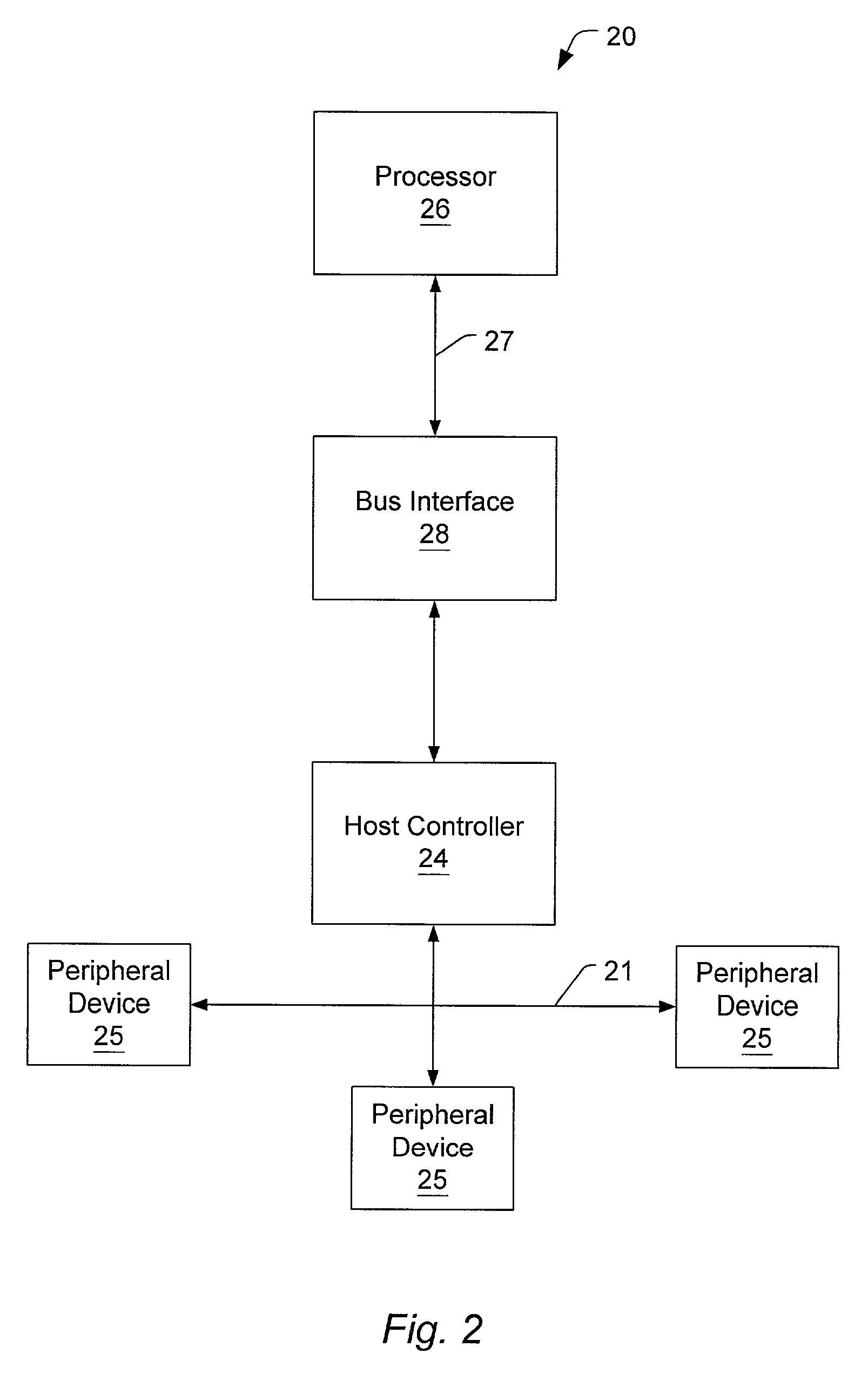
[0026]Turning now to FIG. 2, a block diagram of one embodiment of a computer system is shown. Computer system 20 includes a processor 26 coupled to bus interface unit 28 via processor bus 27. Other embodiments, including those having multiple processors, are possible and contemplated. Bus interface 28 may be coupled to host controller 24, which may be a host controller for a peripheral bus. In one embodiment, host controller 24 and bus interface 28 may be implemented on the same chip, while other embodiments may implement host controller 24 and bus interface 28 on separate chips. Host controller 24 and bus interface 28 may be coupled by various types of buses, such as a peripheral component interconnect (PCI) bus. Peripheral bus 21 may be a serial bus or a parallel bus. Types of serial buses may include, but are not limited to DSL buses and USB buses. Serial buses may also be based on the AC '97 specification discussed above. Host controller 24 may be coupled to one or more peripher...


PUM


Abstract

A method an apparatus for providing capability information to a shared controller. In one embodiment, a peripheral bus host controller may be shared by a plurality of peripheral devices coupled to a peripheral bus. The peripheral devices may include coder/decoder (codec) circuitry, and may be implemented using a riser card. The host controller may be configured to query the bus for peripheral devices by reading each address on the bus. During the querying process, the host controller may detect one or more peripheral devices coupled to the bus. Following the completion of the querying of the bus, the host controller may then begin reading configuration information from each of the detected devices. The host controller may employ one or more of several different techniques in order to read configuration information from the peripheral device. The configuration information at a minimum includes a device identifier, which may identify the vendor and the function of the device. Additional information needed to configure the device to communicate over the peripheral bus may also be obtained with a read of the device, or various lookup mechanisms, such as a lookup table or a tree-like data structure. After configuration information has been obtained for each device coupled to the bus, the host controller may dynamically configure each of the devices for communication over the bus, thereby allowing the flexibility to enumerate riser cards and add new functions through peripheral devices to the computer system in which the bus is implemented.

Description

BACKGROUND OF THE INVENTION[0001]1. Field of the Invention[0002]This invention relates to computer systems, and more particularly, to the identification and configuration of peripheral devices coupled to a peripheral interconnect bus.[0003]2. Description of the Related Art[0004]As the complexity of computer technologies grows and more, improved features are available to users of personal computers, demand for these features increases. PC (personal computer) users also demand that these features be made available at a low cost. These pressures force PC designs to use higher levels of integration throughout the system. The need for a higher level of integration may lead to the development of new types of peripheral buses and I / O (input / output) concepts.[0005]One of the subsystems which has been targeted for increased integration is the audio / modem subsystem. Integration of the audio / modem subsystem into the motherboard by physically soldering components of the subsystem to the motherb...

Claims


Application Information

Patent Timeline
Patent Type & Authority Patents(United States)
IPC IPC(8): G06F13/00G06F3/00
CPCG06F13/385
Inventor COLE, TERRY LYNNGULICK, DALE E.MALECK, TIMOTHY C.BARTH, FRANKWINKLER, JOERG
Owner ADVANCED MICRO DEVICES INC
Why Eureka
Try Eureka