Carafe with contents volume indicator

a technology of contents volume indicator and carafe, which is applied in the field of carafes, can solve the problems of difficult cleaning for users of both structures, difficulty in accurately determining the level of liquid within the vacuum bottle, and difficulty in cleaning the user's experience of both structures, so as to maximize the efficiency of the effect of maximizing the efficiency of the effect of the carafe and accurately determining the level of the contents inside the cara

Active Publication Date: 2007-01-16
THERMOS LLC
View PDF11 Cites 22 Cited by
  • Summary
  • Abstract
  • Description
  • Claims
  • Application Information

AI Technical Summary

Benefits of technology

[0008]It is the principal object of the invention to provide a new and improved carafe that includes provision for accurately determining the level of the contents within the carafe. More specifically, it is an object of the invention to provide such a carafe of the type that includes a vacuum bottle for insulating purposes, which vacuum bottle is provided with a radiation reflective coating to maximize its efficiency. It is particularly an object of the invention to provide such a carafe with an accurate low cost, level indicating means whereby the level of the contents of the carafe may be accurately determined without removal of a stopper or the like and in varying light conditions.
[0009]An exemplary embodiment of the invention achieves the foregoing objects in a vacuum bottle assembly for use in dispensing beverages which include a vacuum bottle having an inner liner, an outer body about the inner liner in spaced relation thereto and sealed to the inner liner to define a vacuum space between the outer body and the inner liner. The outer body and the inner liner are formed of a transparent or translucent material and a covering of reflective material is located on at least one of the outer body and the inner liner to minimize radiation heat transfer between the interior of the inner liner and the exterior of the outer body. A container is provided that has a bottom and an upstanding side wall terminating in a dispensing outlet which is remote from its bottom. The container receives and houses the vacuum bottle. A transparent or translucent window is located in the side wall of the container and extends upwardly from a lower location at or above the bottom of the container to an upper location at or below the dispensing outlet. An interruption is placed in the reflective material covering the vacuum bottle which is of a size and shape roughly approximating that of the window and which is aligned therewith. An indicator is disposed within the vacuum bottle which is of a color that contrasts with the color of a liquid contained within the inner liner and is aligned with both the window and the interruption so as to be visible therethrough to provide an indication of the level of a liquid contained within the inner liner.

Problems solved by technology

In either case, the level of liquid within the vacuum bottle cannot be readily judged when the stopper is in place and even with it is removed, the reflective covering makes an accurate determination difficult.
Users of both of these structures experience difficulty in cleaning the pipe that provides the indication of liquid level.
Furthermore, they are complicated to manufacture and accordingly expensive because of the special need to provide openings in the bottom of the vacuum bottle as well as the provision of several additional parts that are necessary to connect the level gauge constituted by the glass pipe to a dispensing opening and to the interior vacuum bottle.

Method used


Image

  • Carafe with contents volume indicator
  • Carafe with contents volume indicator
  • Carafe with contents volume indicator

Examples


Embodiment Construction

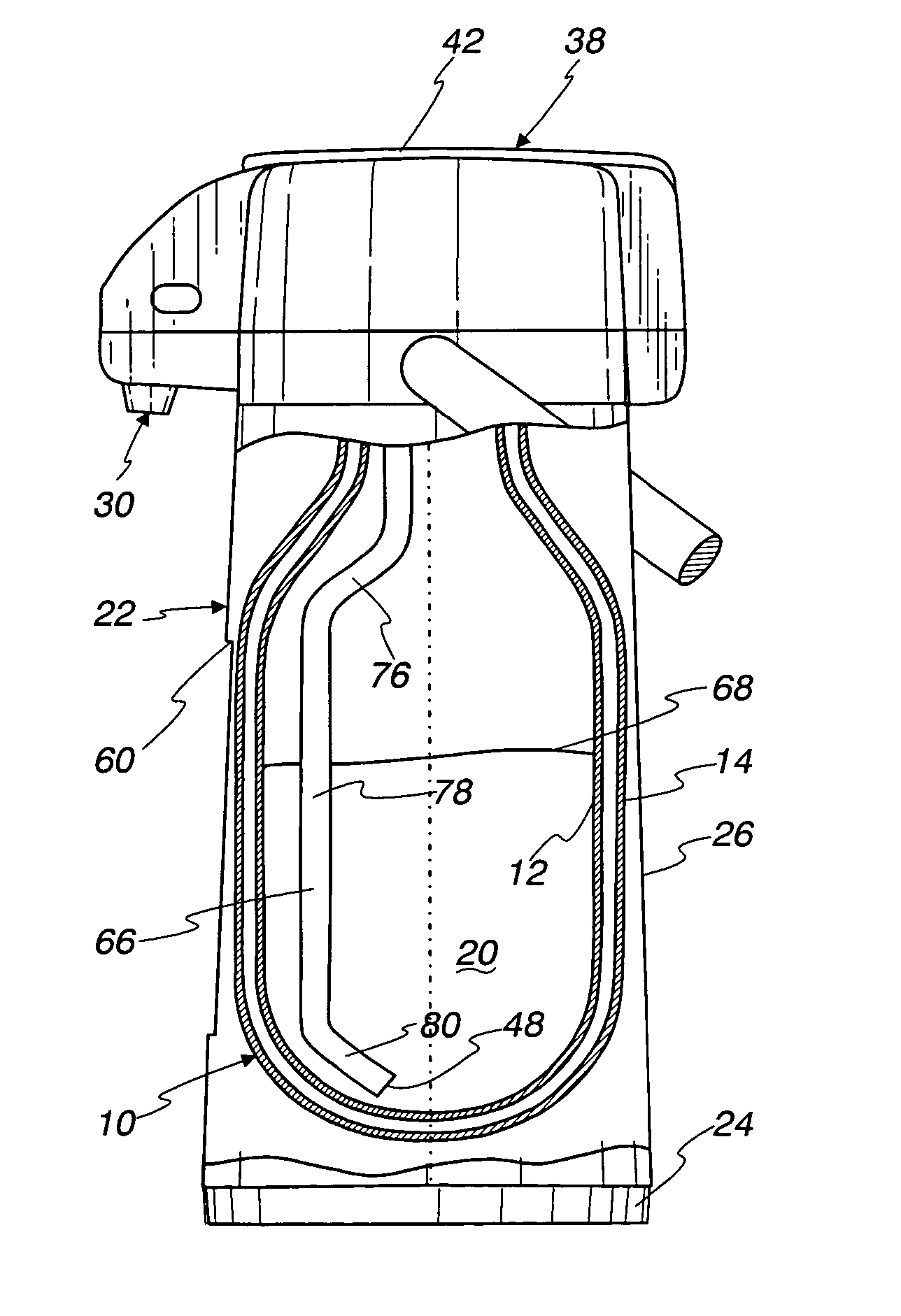
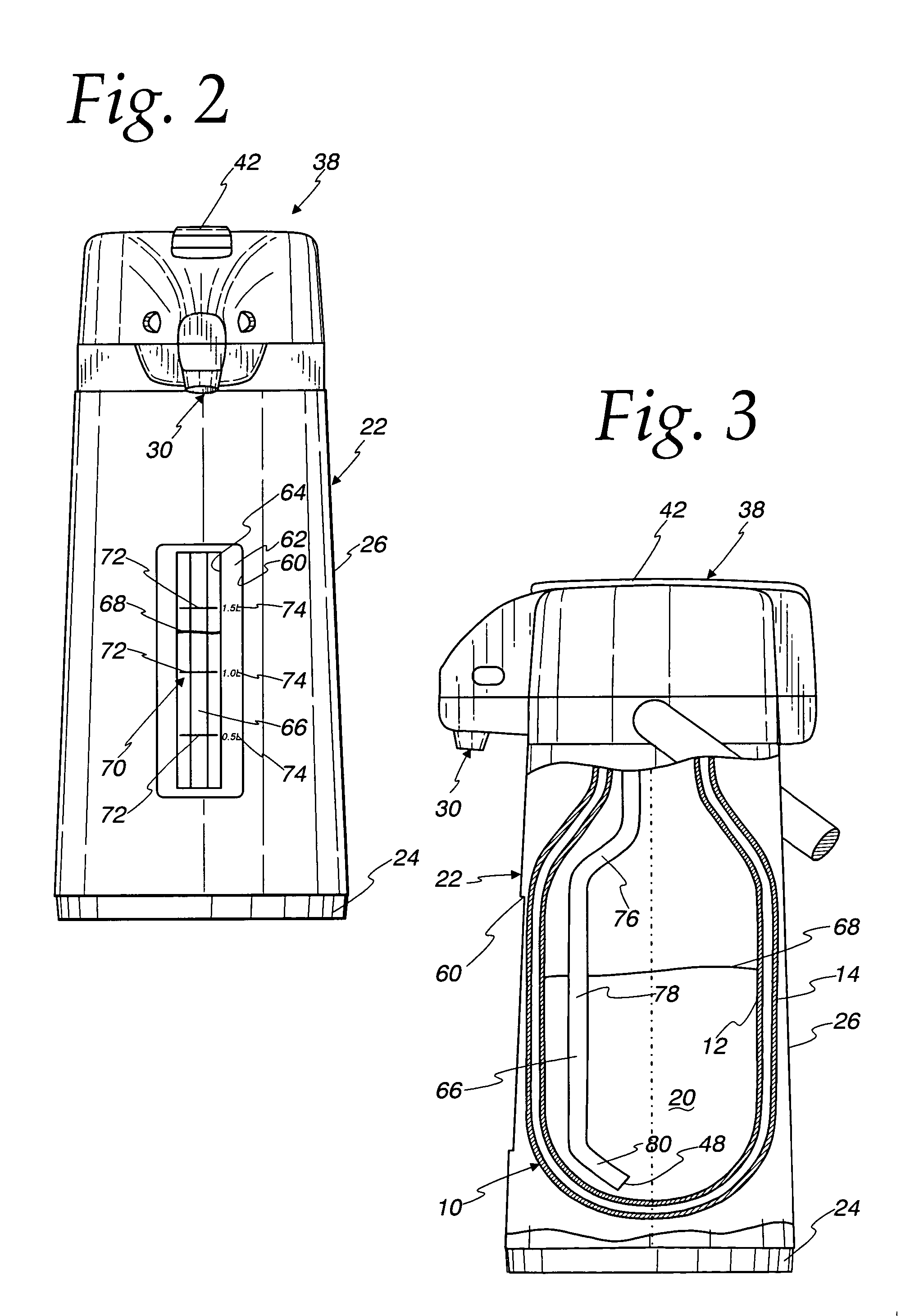
[0032]Exemplary embodiments of the invention will be described in the environment of a so-called “pump pot” type of carafe for dispensing beverages. However, it is to be understood that the invention may be used with utility in other types of carafes and / or vacuum bottle assemblies of the type having an internal vacuum bottle made of a transparent or translucent inner liner and outer body, one or both of which is coated with reflective material for the purpose of minimizing heat loss from the interior of the vacuum bottle to the exterior thereof by a radiation heat transfer. Thus, no limitation to pump pot types of carafe is intended except insofar as expressly stated in the appended claims.

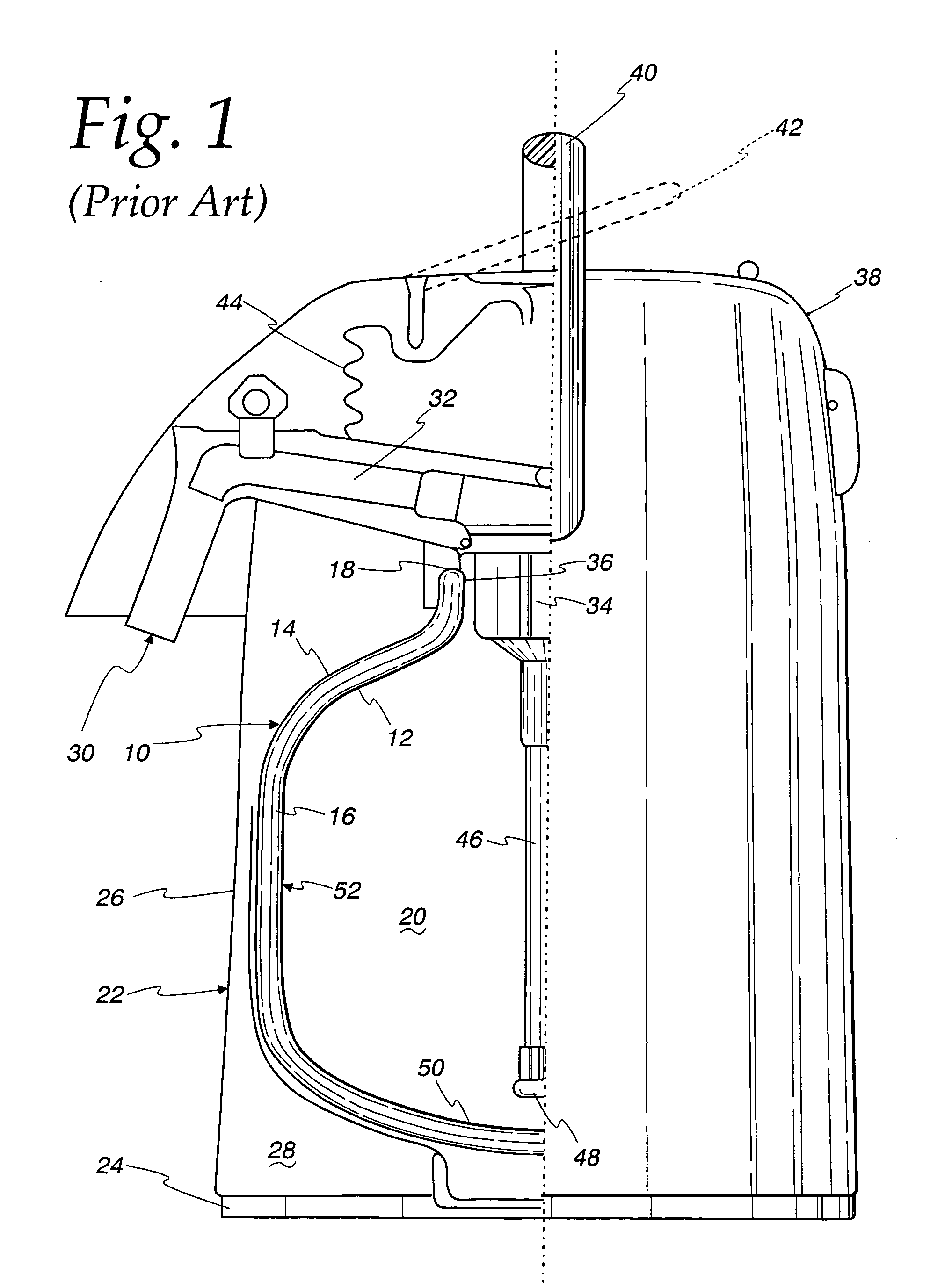
[0033]Turning now to FIG. 1, a conventional pump pot carafe is illustrated and seen to include a vacuum bottle, generally designated 10, including an inner liner 12 surrounded by an outer body 14 with a vacuum space 16 between the two. In the usual case, the inner liner 12 and the outer body 14 a...


PUM


Abstract

An inexpensive, readily visible indicator for liquid levels in a vacuum bottle that includes a coating of reflective material to minimize radiation heat transfer from the interior of the vacuum bottle to the exterior of the assembly. The vacuum bottle assembly includes a container receiving the vacuum bottle and a transparent or translucent window is located in the side wall of the container and in alignment with an interruption in the reflective coating. An indicator is located within the vacuum bottle and is aligned with both the windows and the interruption so as to be visible therethrough to provide an indication of the level of the liquid contained within the inner liner of the vacuum bottle.

Description

FIELD OF THE INVENTION[0001]This invention relates to carafes, and more specifically, to carafes of the so-called “pump pot” type.BACKGROUND OF THE INVENTION[0002]Most high quality carafes available today include a vacuum insulated glass filler or vacuum bottle. The vacuum bottle, as is well known, is made of an inner liner surrounding by an outer body base relation thereto so as to define a vacuum space. The outer body is sealed to the inner liner to maintain the vacuum and typically, one or more of the outside body and the inside liner, usually the inside liner, is provided with a radiation reflective coating, such as silver plating, to minimize heat lost through radiation. The vacuum bottle thus constructed is in turn housed in a protective container that will typically will have a bottom and an upstanding side wall with a more or less decorative surface and which terminates in a dispensing opening in fluid communication with the interior of the vacuum bottle.[0003]In some cases,...

Claims


Application Information

Patent Timeline
Patent Type & Authority Patents(United States)
IPC IPC(8): B67D5/22B65D25/56A47J41/02B67D1/04B67D7/22G01F23/02
CPCG01F23/02B67D1/0425
Inventor MURAKAMI, YASUHIROHIROSE, MASATO
Owner THERMOS LLC
Why Eureka
Try Eureka