Automobile seat

a technology for automobiles and seats, applied in the direction of chairs, pedestrian/occupant safety arrangements, vehicular safety arrangements, etc., can solve the problems of user discomfort, ratchet mechanism cannot allow the headrest to return to its original position, and whiplash injuries, etc., to reduce the load on the neck

Inactive Publication Date: 2007-01-16
DELTA KOGYO CO LTD
View PDF11 Cites 22 Cited by
  • Summary
  • Abstract
  • Description
  • Claims
  • Application Information

AI Technical Summary

Benefits of technology

[0014]It is accordingly an objective of the present invention to provide an automobile seat of a simple construction capable of moving the headrest forwards in the event of a rear-end collision and returning it to its original position after the rear-end collision, wherein a desired clearance is ensured between the head and the headrest in the normal condition. This automobile seat causes the headrest to return to the original position with a resistance, making it possible to reduce a load on the neck.
[0015]In accomplishing the above and other objectives, the automobile seat according to the present invention includes a seat cushion frame, a side frame mounted on the seat cushion frame, and a seat back frame mounted on the side frame so as to be rotatable within a limited angle. An elastic member is mounted on one of the side frame and the seat back frame, while a guide portion having a holding portion for holding the elastic member is formed on the other of the side frame and the seat back frame. The seat back frame is fixed to the side frame in a normal sitting condition in which the elastic member is held in the holding portion. If a load greater than a predetermined value is inputted from behind, a lower portion of the seat back frame is pushed by a lumbar part of a seat occupant upon a rearward movement of the seat occupant to thereby deform the elastic member, which in turn leaves the holding portion and moves rearwards along the guide portion, thus causing the seat back frame to rotate with respect to the side frame and causing the headrest to move forwards.
[0024]According to the present invention, the seat back frame is fixed to the side frame in the normal sitting condition by holding the elastic member in the holding portion. If a load greater than a predetermined value is inputted from behind due to, for example, a rear-end collision, a lower portion of the seat back frame is pushed by a lumbar part of a seat occupant upon a rearward movement of the seat occupant to thereby deform the elastic member, which in turn leaves the holding portion and moves rearwards along the guide portion, thus causing the seat back frame to rotate with respect to the side frame and causing the headrest to move forwards. Accordingly, the elasticity of the elastic member acts to prevent the neck of the seat occupant from being damaged. In addition, the headrest is held at a forward position by means of the elasticity of the elastic member, and when a rebound (weight shift) after the collision returns the headrest to its original position, a resistance is produced to some extent, making it possible to reduce a load on the neck.

Problems solved by technology

Accordingly, a load is applied to the user's neck, resulting in a whiplash injury.
In this case, however, the user's head is often brought into contact with the headrest even in the normal sitting condition, and even a slight movement of the head causes the head to interfere with the headrest, making the user uncomfortable.
The ratchet mechanism cannot allow the headrest to return to its original position after the rear-end collision.
Because the headrest is held at the forward position after the rear-end collision, the impact on the head is reduced to some extent, but it is still insufficient.
However, the mechanism is complicated and is hence costly.

Method used


Image

  • Automobile seat
  • Automobile seat
  • Automobile seat

Examples


embodiment 1

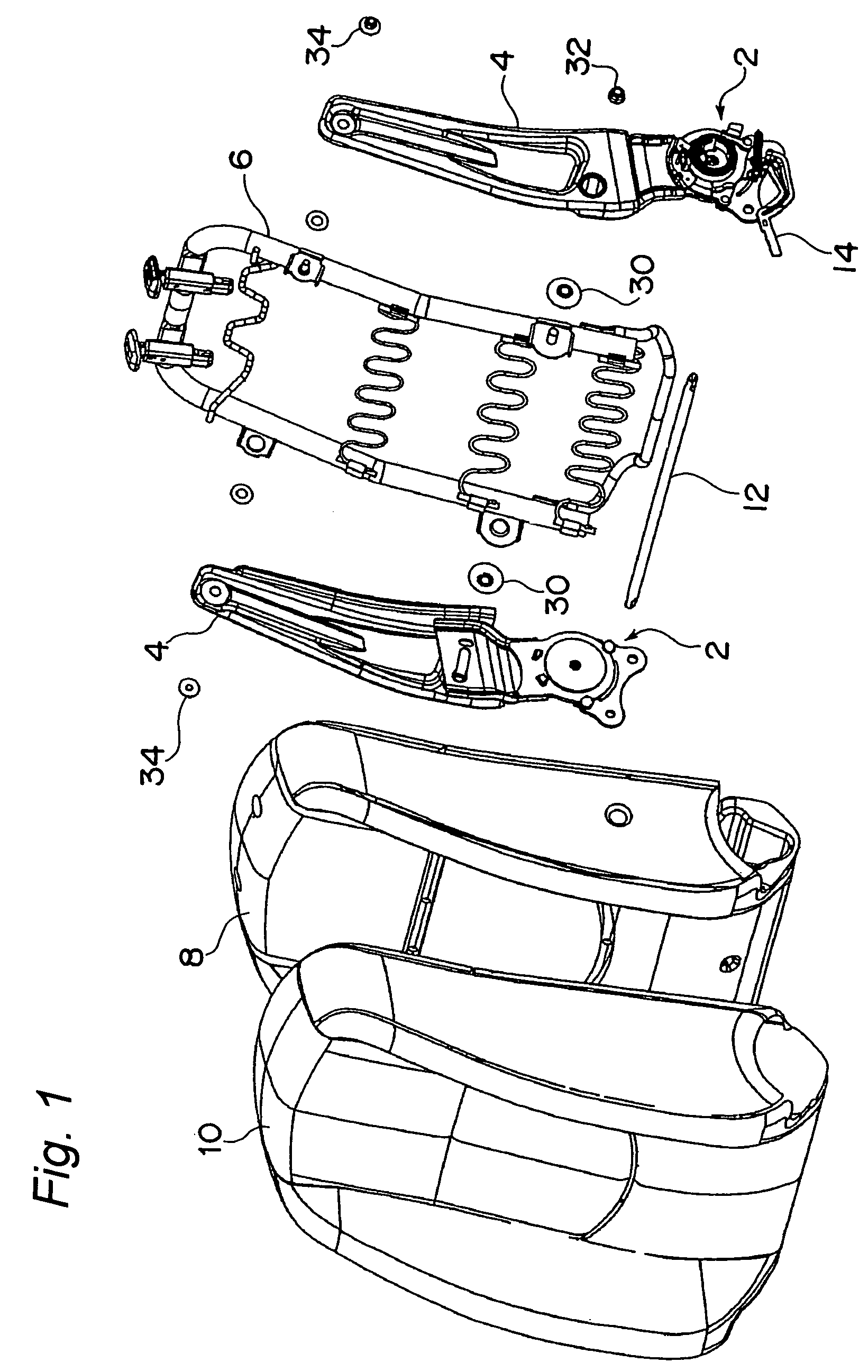
[0047]FIG. 1 depicts a seat back of an automobile seat according to a first embodiment of the present invention, which is tiltably mounted on a seat cushion (not shown). The seat back includes a pair of side frames 4 mounted on a seat cushion frame (see FIG. 11 or 12) via respective recliner adjusters 2, a seat back frame 6 mounted on the pair of side frames 4, a pad material 8 mounted on the seat back frame 6, and a skin material 10 covered on the pad material 8. A headrest 11 (see FIG. 4) is mounted on an upper portion of the seat back frame 6.

[0048]The pair of recliner adjusters 2 are connected to each other via a connecting shaft 12. Operation of an operation lever 14 mounted on one of the recliner adjusters 2 allows the side frames 4 to be set to a desired angle.

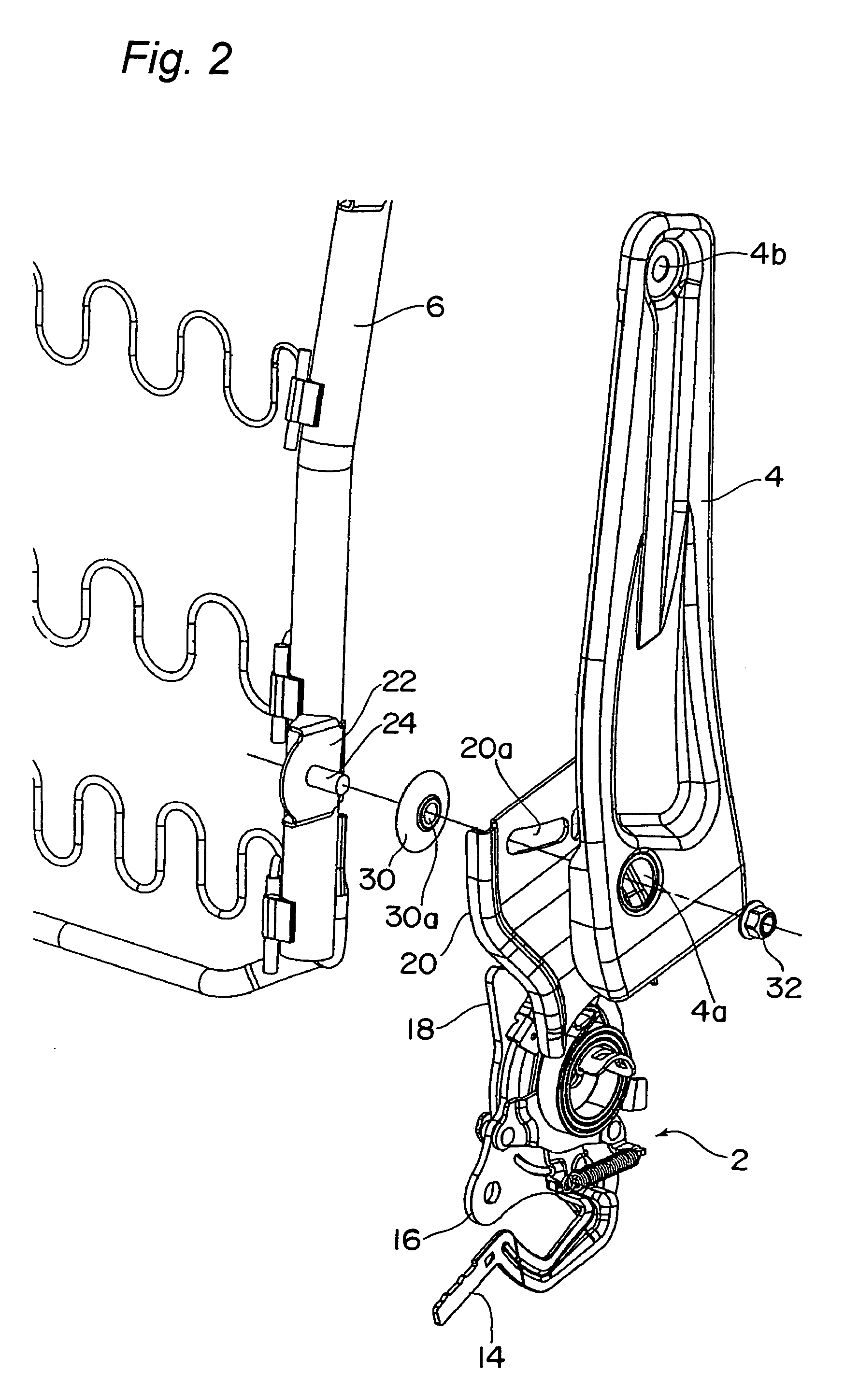
[0049]As shown in FIGS. 2 and 3, each of the recliner adjusters 2 includes a lower bracket 16 secured to the seat cushion frame and an upper bracket 18 rotatable relative to the lower bracket 16. Because the present inv...

embodiment 2

[0073]FIGS. 11 and 12 depict an automobile seat according to a second embodiment of the present invention. Only differences between the first and second embodiments are discussed hereinafter.

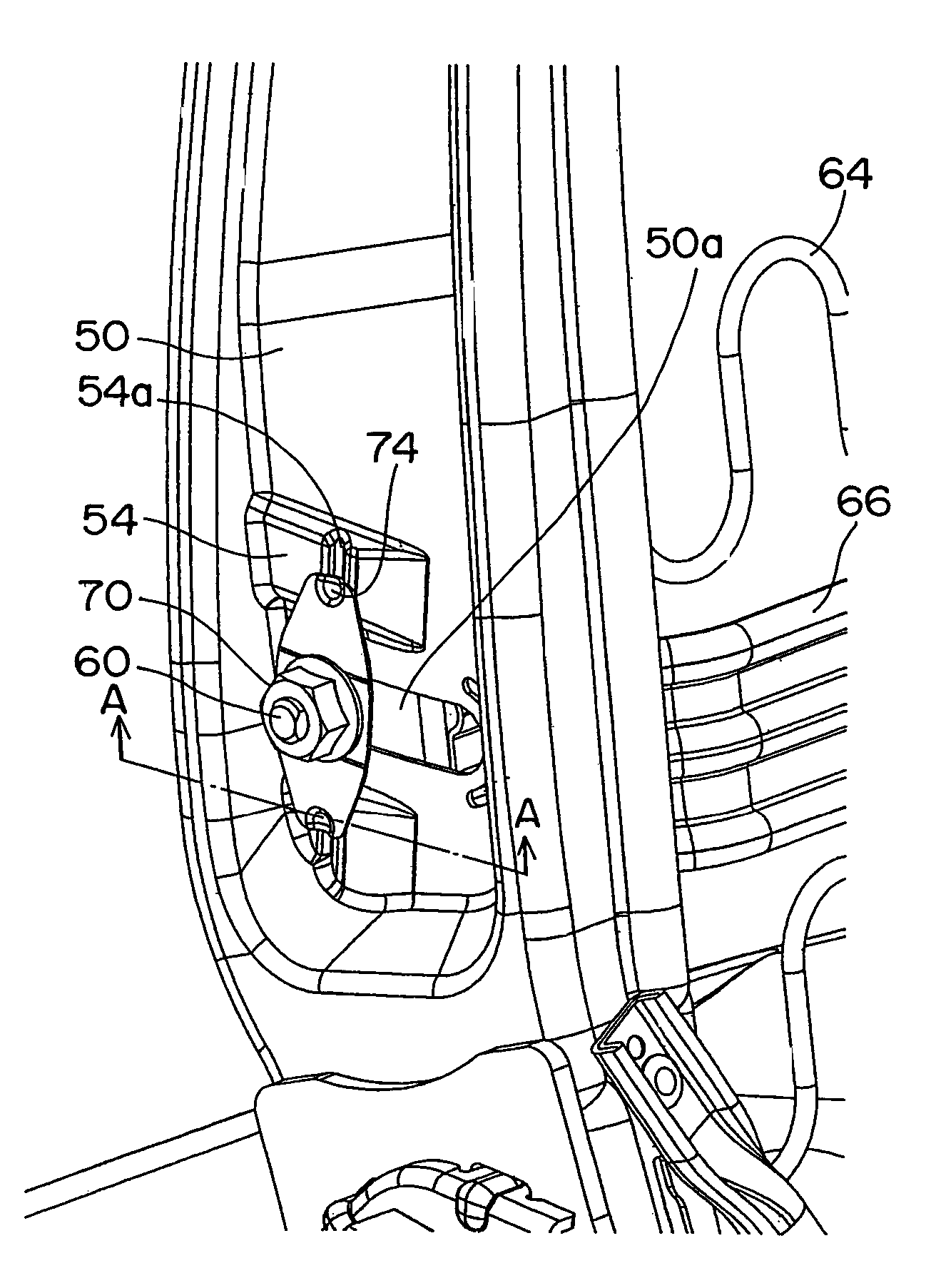
[0074]A side frame 50 is secured at a lower portion thereof to an upper bracket 18 of a recliner adjuster 2. The side frame 50 has a guide groove (guide portion) 50a defined therein in which a bolt (explained later) secured to a seat back frame 52 in the vicinity of a lower end thereof is loosely inserted.

[0075]As shown in FIG. 13, the side frame 50 has two ridges 54 formed on an outer surface thereof on respective sides of the guide groove 50a except a rear end portion thereof so as to extend generally parallel to the guide groove 50a. Each ridge 54 has a recess (elastic member holder) 54a defined at an intermediate portion thereof for holding an elastic member (explained later). The side frame 50 has a bolt insertion hole 50b defined therein at an upper portion thereof. The guide groove 50a re...


PUM


Abstract

An automobile seat includes a seat cushion frame, a side frame, and a seat back frame mounted on the side frame to be rotatable within a limited angle. An elastic member and a guide portion having an elastic member holding portion are mounted on the side frame and the seat back frame. The seat back frame is normally fixed to the side frame with the elastic member held in the holding portion, but when a load greater than a predetermined value is inputted from behind, a lower portion of the seat back frame is pushed rearward by a lumbar part of a seat occupant to thereby deform the elastic member, which in turn leaves the holding portion and moves rearward along the guide portion, thus causing the seat back frame to rotate with respect to the side frame and causing the headrest to move forward.

Description

BACKGROUND OF THE INVENTION[0001]1. Field of the Invention[0002]The present invention relates to an automobile seat capable of preventing a seat occupant from suffering a whiplash injury when an automotive vehicle has come into a rear-end collision.[0003]2. Description of the Related Art[0004]Automobile seats generally have a headrest mounted on an upper portion of a seat back. When a user sits on a seat, a predetermined clearance is present between the user's head and the headrest, but when an automobile vehicle has come into a rear-end collision, the user's body moves forwards, while the user's head remains back. Accordingly, a load is applied to the user's neck, resulting in a whiplash injury.[0005]It is possible to reduce the clearance between the user's head and the headrest to minimize the injury. In this case, however, the user's head is often brought into contact with the headrest even in the normal sitting condition, and even a slight movement of the head causes the head to...

Claims


Application Information

Patent Timeline
Patent Type & Authority Patents(United States)
IPC IPC(8): B60N2/42A47C7/38A47C7/14A47C7/44B60N2/427B60N2/48B60N2/90B60R21/055
CPCB60N2/42745B60N2/682B60N2/4885B60N2/4805B60N2/888B60N2/806
Inventor KAWASHIMA, YOSHIHITO
Owner DELTA KOGYO CO LTD
Why Eureka
Try Eureka