Flashback blood collection needle with needle shield

a blood collection and shield technology, applied in the field of shielded blood collection needle assembly, can solve the problems of phlebotomists unnecessarily withdrawing needles and starting blood collection procedures, wasting time, and wasting tim

Inactive Publication Date: 2007-01-16
BD MEDICAL PROD
View PDF170 Cites 56 Cited by
  • Summary
  • Abstract
  • Description
  • Claims
  • Application Information

AI Technical Summary

Problems solved by technology

One problem with collecting fluid from a patient relates to uncertainty during attempts to access the proper source of fluid in the patient.
The initial flow of blood along the long needle cannula and into the evacuated tube may take a relatively long time based on several factors, including the relative pressure levels and the length and cross-sectional dimensions of the needle cannula.
Thus, the phlebotomist may unnecessarily withdraw the needle and start the blood collection procedure again.
As a result, time is wasted and trauma for the patient is increased.
Shields of this type create the risk of an accidental needle stick during shielding if the shield is misaligned with the needle cannula.
However, shields of this type can interfere with the normal usage of some medical implements.
However, the existence of a hinged shield on a fluid collection needle assembly with a flashback chamber is intuitively problematic in view of the complexities of providing both shielding and an unobstructed view of the flashback chamber.

Method used


Image

  • Flashback blood collection needle with needle shield
  • Flashback blood collection needle with needle shield
  • Flashback blood collection needle with needle shield

Examples


Embodiment Construction

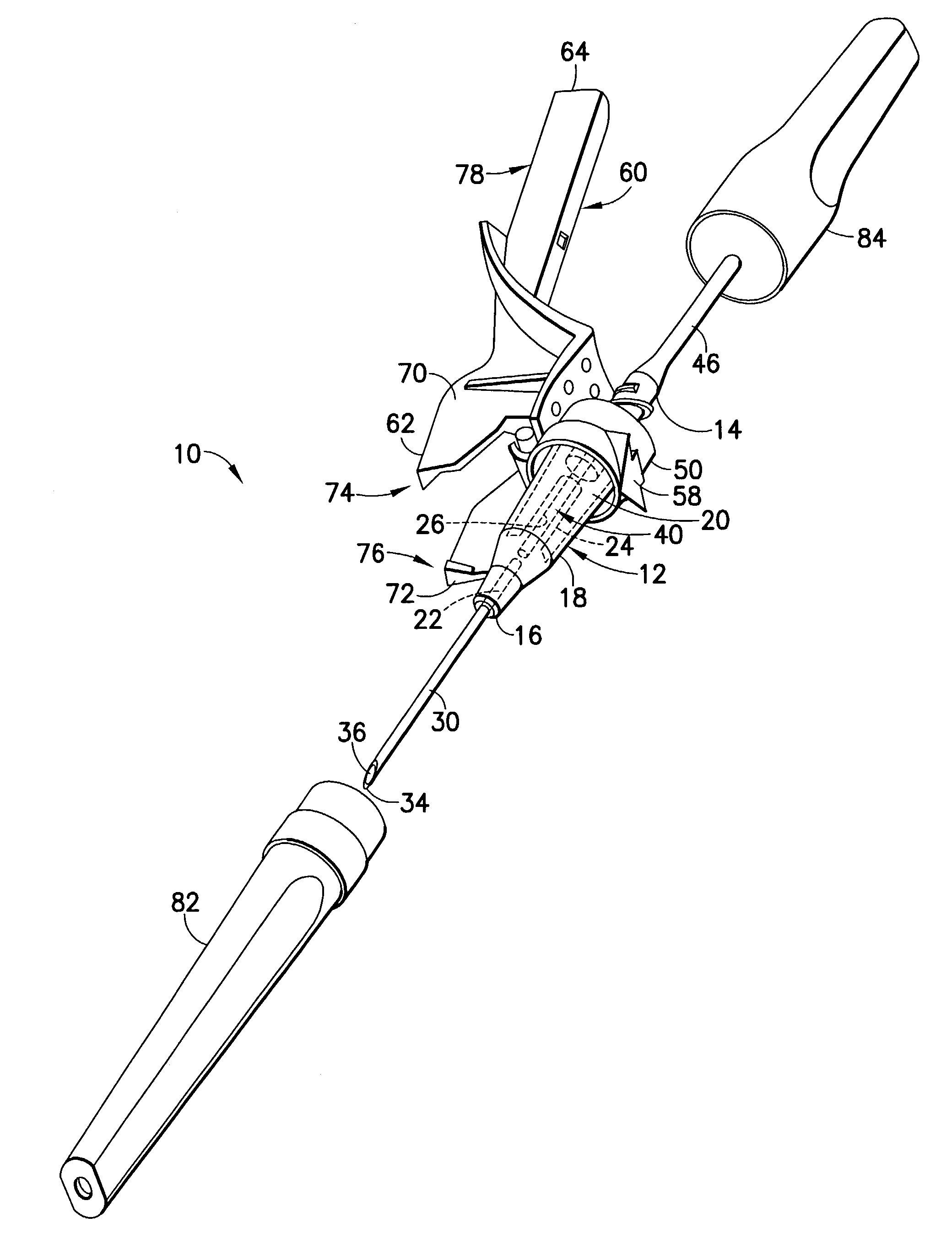
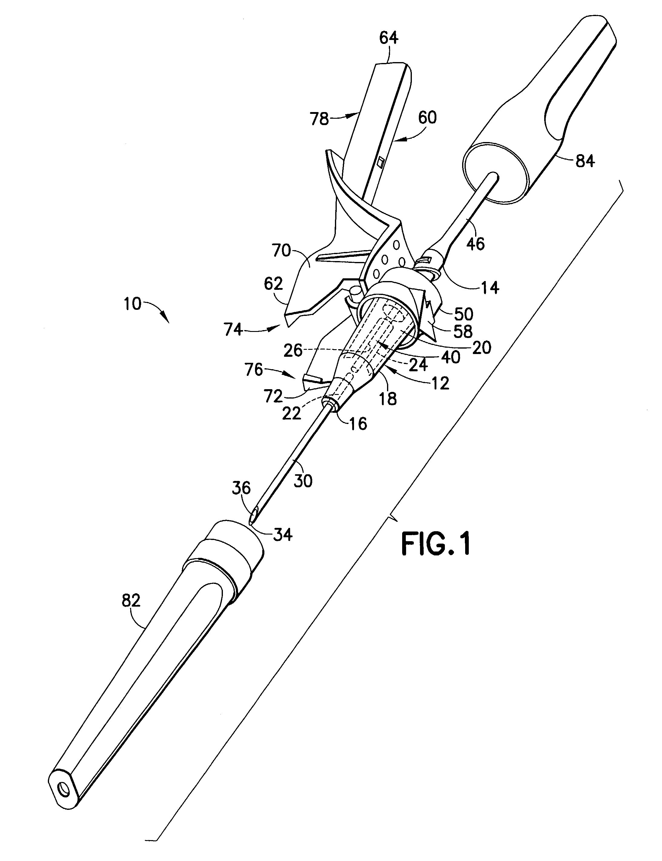
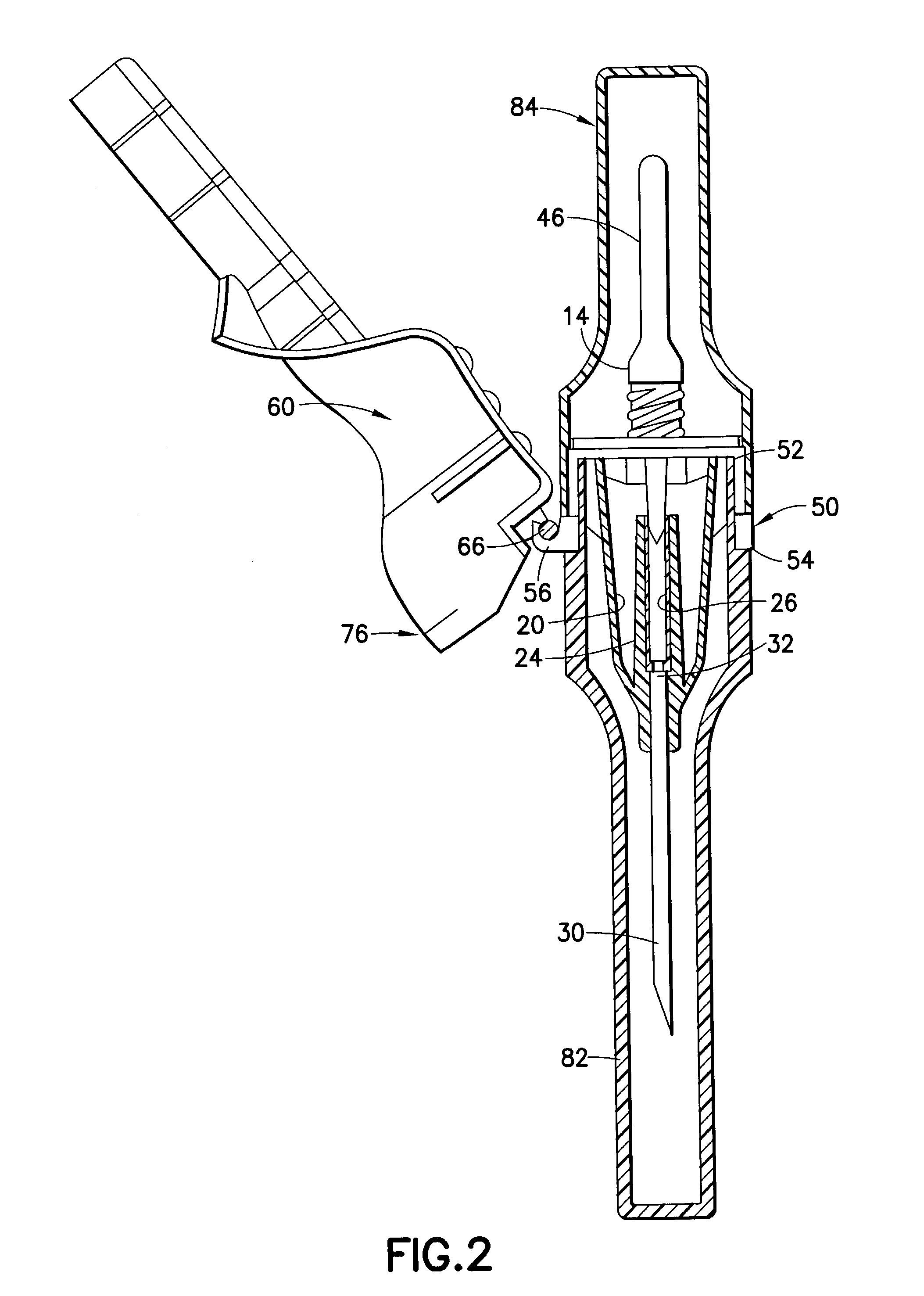
[0017]A needle assembly in accordance with the subject invention is identified generally by the numeral 10 in FIGS. 1–5. Needle assembly 10 includes a housing 12 with a proximal end 14, a distal end 16 and a generally frustum-shaped outer sidewall 18 extending between the ends. Outer sidewall 18 is formed from a transparent or translucent plastic material and defines a chamber 20 within housing 12 between proximal end 14 and distal end 16. A proximal passage (not shown) extends through proximal end 14 of housing 12 and communicates with chamber 20. A distal passage 22 extends through distal end 16 of housing 12 and also communicates with chamber 20. Housing 12 further includes a cylindrical inner sidewall 24 that extends from distal end 16 toward proximal end 14. Inner sidewall 24 is substantially concentrically disposed within outer sidewall 18 and is substantially concentrically generated about distal passage 22. Inner sidewall 24 also is formed from a transparent or translucent p...


PUM


Abstract

The needle assembly is provided with the housing, an IV cannula for accessing a blood vessel and a non-patient cannula for communication with an evacuated tube. A flashback chamber is provided in the housing at or near the distal end of the housing. A shield is hinged to a portion of the housing proximally of the entrance to the flashback chamber. As a result, good visibility of the flashback chamber is achieved. After use, the shield can be rotated into a closed position for surrounding the IV cannula and avoiding accidental needle sticks.

Description

BACKGROUND OF THE INVENTION[0001]1. Field of the Invention[0002]A shieldable blood collection needle assembly with a flashback chamber for providing confirmation of venous entry.[0003]2. Description of Related Art[0004]Needle assemblies are used for collecting specimens of fluid, such as blood, from a patient. Some such needle assemblies are intended for use with an evacuated tube, such as tubes sold under the trademark VACUTAINER™ by Becton Dickinson. Needle assemblies for use with an evacuated fluid collection tube include a needle hub with a proximal end, a distal end and a passage extending between the ends. The needle assembly further includes at least one needle cannula mounted to the needle hub. The needle cannula includes a sharply pointed distal end that projects distally beyond the needle hub, a proximal end that projects proximally beyond the needle hub and a lumen that provides communication between the opposed ends of the needle cannula. Some needle assemblies include s...

Claims


Application Information

Patent Timeline
Patent Type & Authority Patents(United States)
IPC IPC(8): A61M5/178A61B5/15A61M5/32
CPCA61B5/1444Y10S128/919A61M5/3216A61B5/15003A61B5/150213A61B5/150259A61B5/150389A61B5/150496A61B5/150572A61B5/150671A61B5/150717A61B5/150732A61B5/150809A61B5/150816A61B5/150824A61B5/1545A61B5/150587
Inventor LEONG, ALVIN TAN CHEEYAOHAN, JON MOH
Owner BD MEDICAL PROD
Why Eureka
Try Eureka