

Electric device and method
a technology of electric devices and methods, applied in the direction of electric generator control, machines/engines, mechanical equipment, etc., can solve the problems of unfavorable competition with conventional electric power production, single coil of stator winding, and extremely low so as to reduce costs and also the risk of disturbance, and the frequency of induced current can be increased. , the effect of simple design of winding and current passing
- Summary
- Abstract
- Description
- Claims
- Application Information
AI Technical Summary
Benefits of technology
Problems solved by technology
Method used
Image

Examples
Embodiment Construction
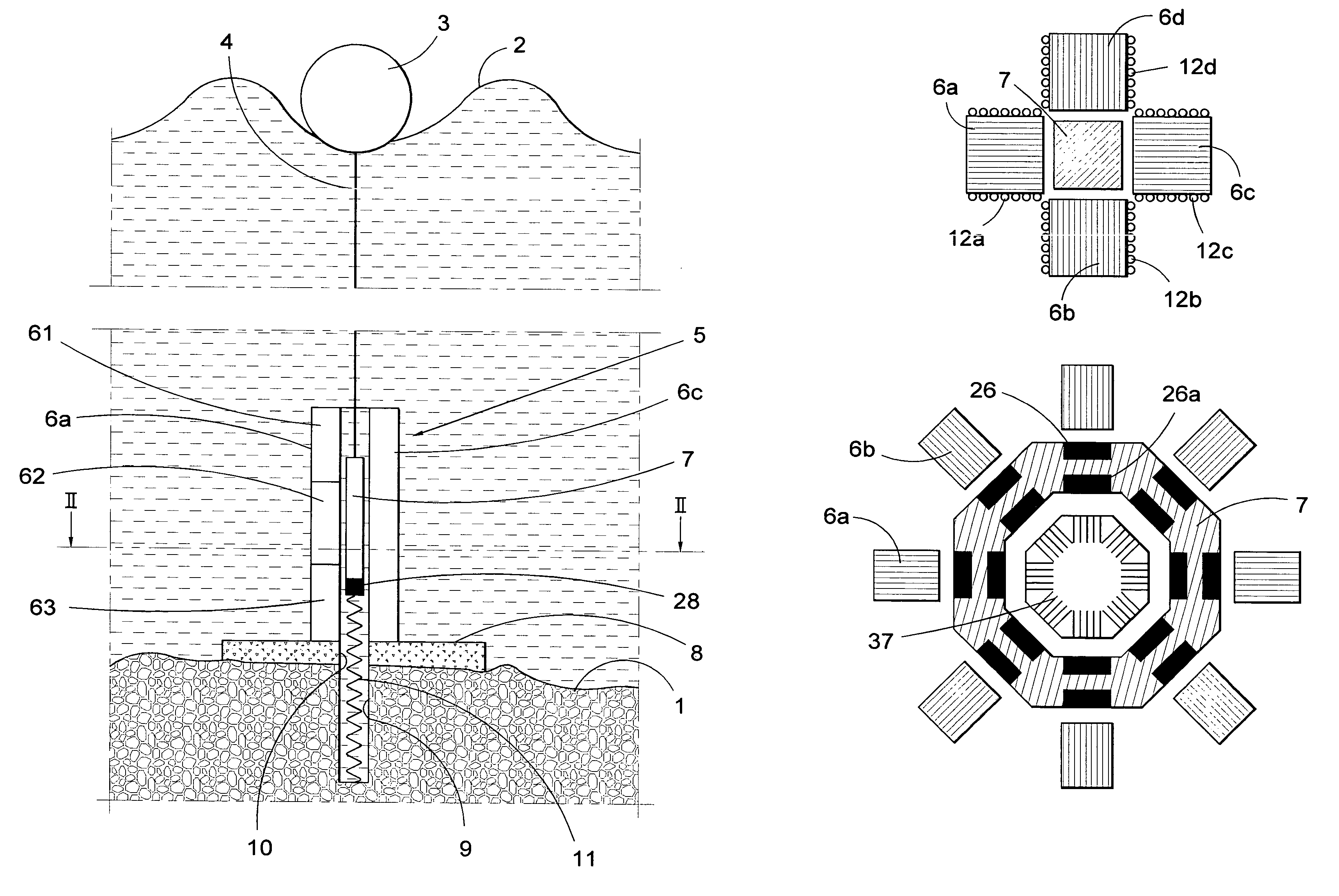
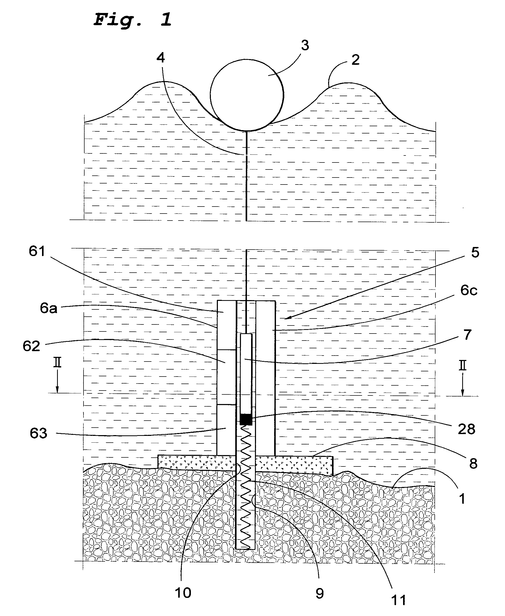
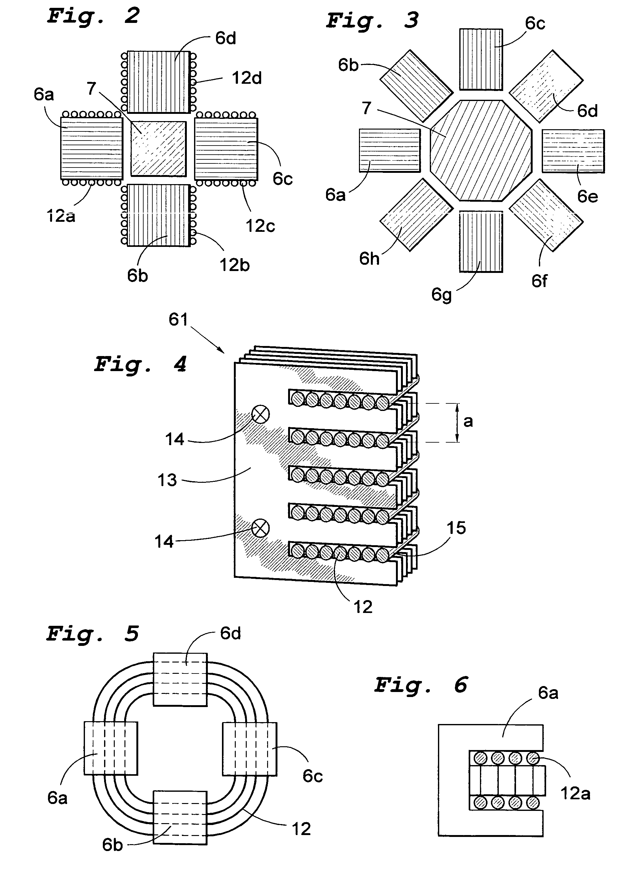
[0018]The objective set has been achieved in accordance with the first aspect of the invention in that the wave-power unit described in the preamble to claim 1 comprises the special features that the rotor is permanently magnetic and that the stator comprises a winding forming a plurality of poles distributed in the direction of movement of the rotor. Accommodating the winding in the stator and making the rotor permanently magnetic enables the simplest possible construction of the movable parts of the unit, thereby reducing costs and also the risk of disturbances. It is also simpler to design the winding and pass on the current when the winding is placed in the stator. Thanks also to a plurality of poles being arranged one after the other, the frequency of the induced current can be increased, which is a considerable advantage in view of the fact that the frequency of the to-and-fro movement is low. The claimed wave-power unit thus offers a financially competitive method of extracti...
PUM
 Abstract
Description
Claims
Application Information