

Image processing method, system and apparatus, and storage medium
a technology of image processing and storage media, applied in the direction of digital output to print units, visual presentation using printers, instruments, etc., can solve the problems of various problems affecting the image forming unit 108 which is utilized for outputting, and achieve the effect of improving the quality of output images
- Summary
- Abstract
- Description
- Claims
- Application Information
AI Technical Summary
Benefits of technology
Problems solved by technology
Method used
Image

Examples
first embodiment
[0051]FIG. 3 is a block diagram showing the configuration of an image processing system according to a first embodiment of the present invention.
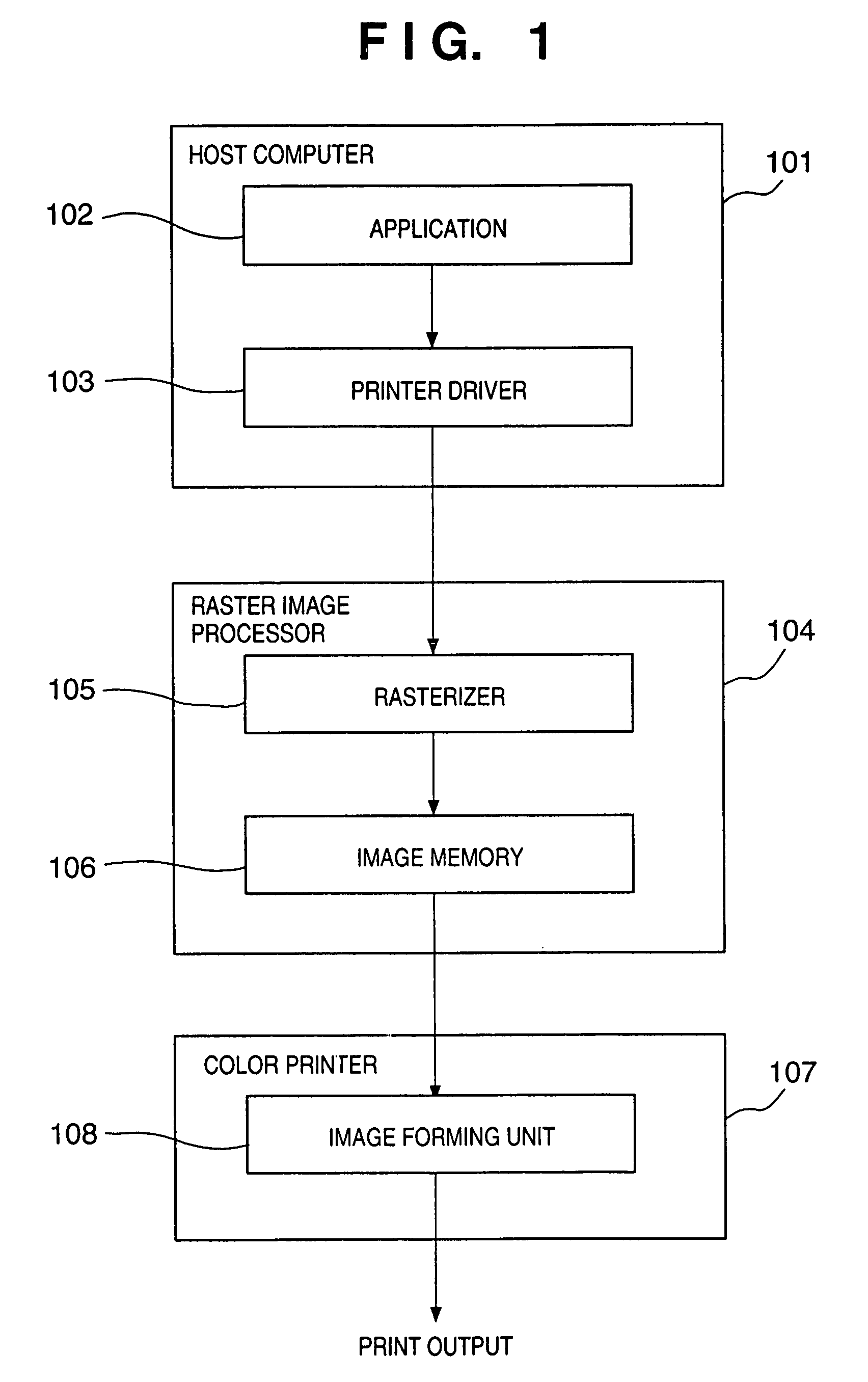
[0052]In this respect, in FIG. 3, reference numerals 10 to 15 are the same as reference numerals 101 to 106, respectively in FIG. 1, and reference numerals 18 and 19 are the same as reference numerals 107 and 108 in FIG. 1, respectively.
[0053]The present embodiment is characterized by an attribute map memory 16 and an image processing unit 17. In this case, the image processing unit 17 is shown such that it independently exists, but it may be configured such that it is included in a raster image processor 13 or a color printer 18.
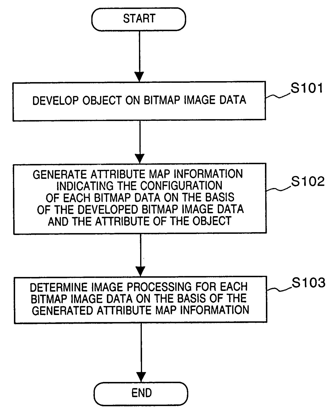
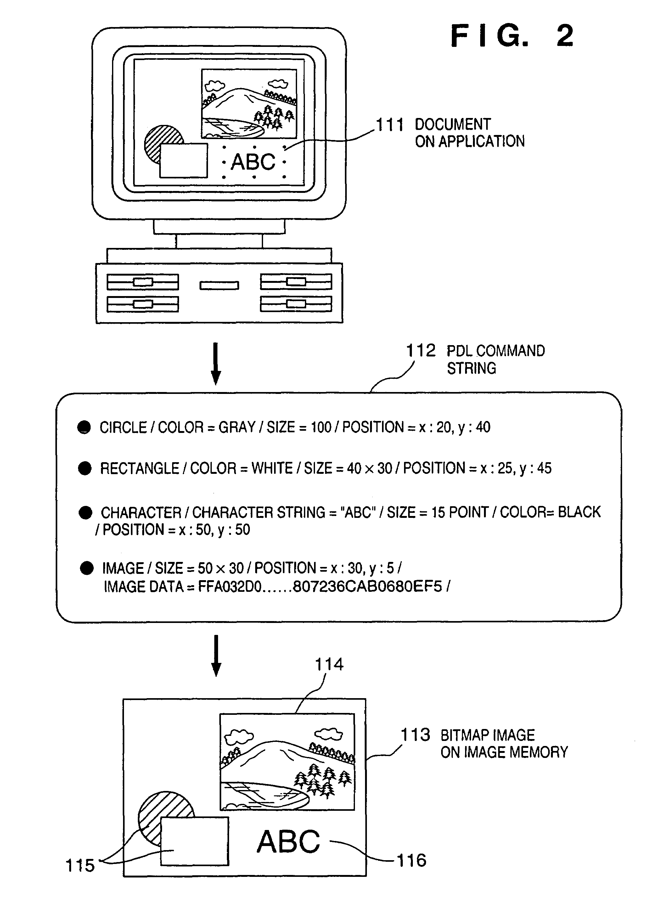
[0054]A rasterizer 14 generates a bitmap image on an image memory 15 on the basis of commands associated with individual components (hereinafter called “objects”) configuring an image. At this time, attribute map information is generated on the basis of the attributes of the objects and the generated bitmap image u...
second embodiment
[0083]Hereinafter, with reference to the accompanying drawings, the detailed description will be made of a second preferred embodiment according to the present invention.
[0084]FIG. 14 is a block diagram showing the configuration of an image processing system according to the second embodiment.
[0085]In FIG. 14, reference numeral 140 denotes a host computer; and 141, an application to be used within the host computer 140. Applications 141, include, for example, word processor software, a drawing system or software, graphic software and the like. Reference numeral 142 denotes a printer driver, which serves as an interface with the printer for outputting characters, graphics and bitmap images from the application 141 to the printer.
[0086]Reference numeral 143 denotes a raster image processor for developing output obtained through the printer driver into image data. Within the raster image processor 143, there are contained a rasterizer 144, an image memory 145 for storing the image data...
third embodiment
[0115]In the second embodiment, the description has been made of a case where there is 1-bit information as the attribute map. However, the attribute information for each pixel of the attribute map is not limited to 1 bit. In a third embodiment, as an example of attribute information including a plurality of bits, the description will be made of a case where 2-bit attribute information has been adopted.
[0116]FIG. 25 is a view showing an example of a data format for attribute information according to the third embodiment. This has 2-bit information consisting of the 0th bit and 1 st bit, and the 0th bit is a bitmap flag, and is the same as described in the second embodiment. More specifically, if the bitmap flag is “1”, it is shown to be a pixel generated from the bitmap object, and if “0”, it is a pixel generated from the vector object, that is, it is shown to be a pixel in the character or graphic image.
[0117]The 1 st bit of the attribute map is a color flag, and if it is 1, it sho...
PUM
 Abstract
Description
Claims
Application Information