Plasma display

a technology of plasma display and display screen, which is applied in the direction of electrical apparatus construction details, television system, coupling device connection, etc., can solve the problem that the plasma display may develop an unacceptable high temperature, and achieve the effect of enhancing the overall dissipation efficiency and increasing heat dissipation

Inactive Publication Date: 2007-01-16
AU OPTRONICS CORP
View PDF17 Cites 104 Cited by
  • Summary
  • Abstract
  • Description
  • Claims
  • Application Information

AI Technical Summary

Benefits of technology

[0015]In the invention, electronic elements with different heat dissipation requirements are disposed in different areas and a dedicated heat dissipation device is provided for these electronic elements requiring increased heat dissipation. Thus, the overall dissipation efficiency of the plasma display is enhanced.

Problems solved by technology

In this structure, as the driver module 120 and the electronic element 140 are disposed on the same circuit board 100, the space and path for heat dissipation may not be sufficient, therefore, the plasma display may develop an unacceptable high temperature.

Method used


Image

  • Plasma display
  • Plasma display
  • Plasma display

Examples


first embodiment

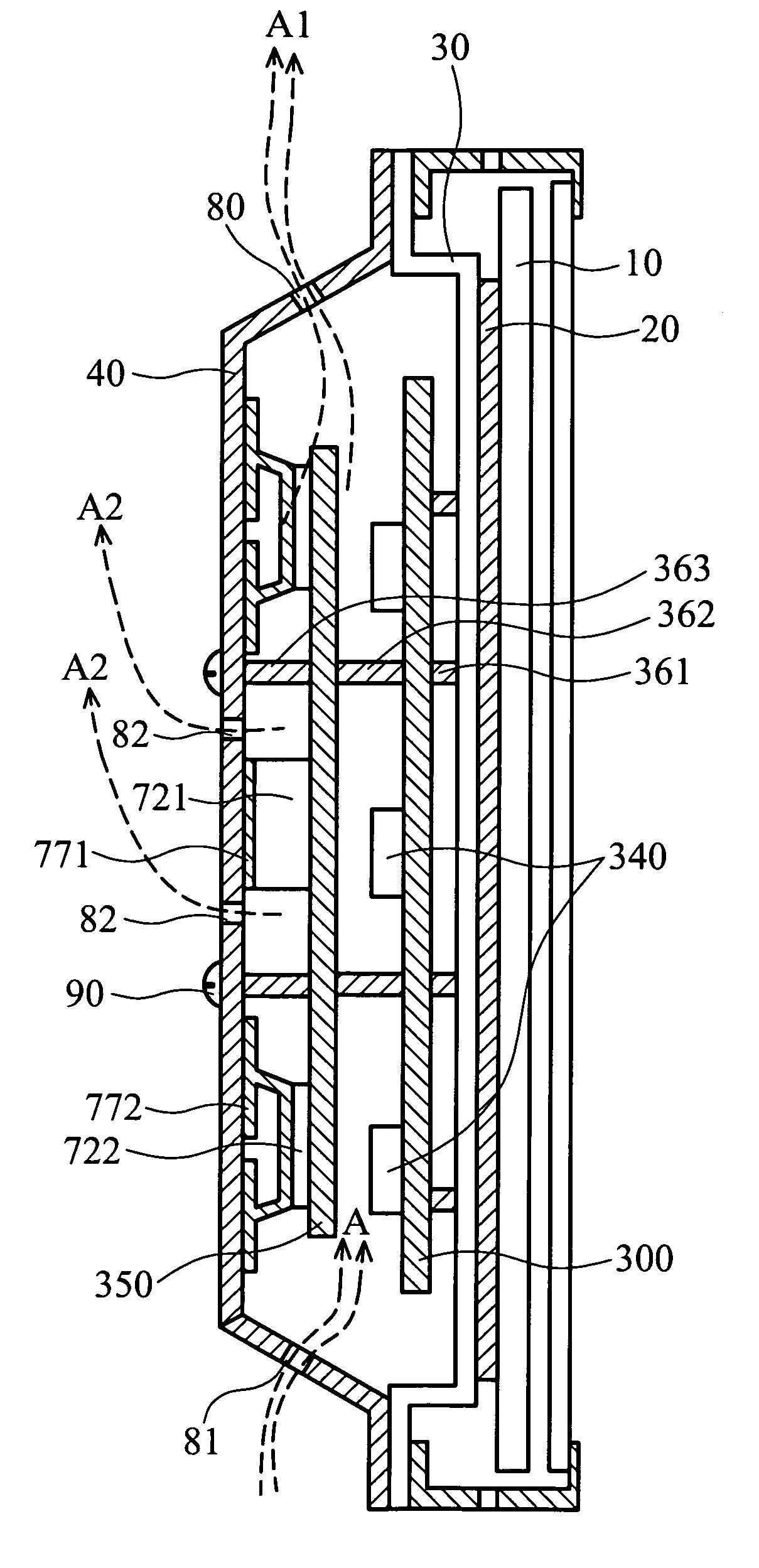
[0026]As shown in FIG. 3, a first circuit board 350 and a second circuit board 300 are accommodated in a space formed by a metal back cover 40 and a base plate 30 of the plasma display. The second circuit board 300 is secured to the base plate 30 via a plurality of supporters 361 and the first circuit board 350 is secured to the second circuit board 300 via a plurality of supporters 362, such that the second circuit board 300 is separated from the first circuit board 350 by an appropriate distance for bearing an electronic element (the third electronic element) 340 thereon. The first circuit board 350 is separated from the back cover 40 by supporter 363 to maintain an appropriate distance therebetween for bearing a driver module (the first electronic element) 320 thereon. As the driver module 320 gives out more heat than the electronic element 340, the driver module 320 makes thermal contact with the back cover 40 via a thermal pad 370 (no adhesive) for heat dissipation by means of ...

second embodiment

[0030]As shown in FIG. 4, according to the structure in the first embodiment, the distance between the first circuit board 350 and the second circuit board 300 is large enough to accommodate electronic element (the fifth electronic element) 380 on the rear of the first circuit board. Other structures are the same as the first embodiment. Thus, space for electronic elements on the circuit board is increased.

third embodiment

[0031]As shown in FIG. 5, a circuit board 500 is secured on the base plate 300 via a supporter 560 and bears a driver module 520 and an electronic element 540, wherein the driver module 520 makes thermal contact with the back cover 40 by a thermal conductive spring element 570 of copper. The heat from the driver module 520 is conducted to the back cover 40 via the thermal conductive spring element 570 to improve dissipation efficiency. The thermal conductive spring element 570 includes a spring portion 571 and a contact portion 572. The spring portion 571 and the contact portion 572 can be integrally formed. The spring portion 571 is configured in a U shape, the legs of which can be elastically deformed. The contact portion 572 is a plate abutting the back cover 40 by the resilient force of spring portion 571. The spring portion 571 provides various options in designing the distance from the driver module 520 to the back cover 40.

[0032]In this embodiment, although the driver module ...


PUM


Abstract

A plasma display. The plasma display comprises a first circuit board and a second circuit board disposed in a space formed by a base plate and a back cover thereof. The first circuit board is mounted on the base plate and bears a first electronic element, the second circuit board is mounted on the first circuit board and bears a second electronic element requiring heat dissipation different from the first electronic element. A thermal conductive device is disposed between the second electronic element and the back cover to dissipate heat from the second electronic element to the back cover. Thereby, the electronic elements requiring different heat dissipation are positioned in divided areas to enhance heat dissipation efficiency.

Description

BACKGROUND OF THE INVENTION[0001]1. Field of the Invention[0002]The present invention relates to a plasma display, and in particular to a plasma display having divided areas for divers electronic elements requiring heat dissipation.[0003]2. Description of the Related Art[0004]A display panel, electronic elements and driver modules in a driver circuit are main heat sources of a plasma display. In a conventional plasma display, as shown in FIG. 1, a display panel 10 is secured to a metal base plate 30 via a thermal pad 20. The base plate 30 and the back cover 40 of the plasma display form a closed space accommodating a circuit board 100. Heat produced by the display panel 10 is conducted to the metal back cover 40 via the thermal pad 20 and base plate 30 for dissipation. Heat from a driver module 120 and an electronic element 140 is evacuated by airflow L via a vent 180 and a fan 190 to the exterior. In general, the driver module 120 requires more heat dissipation than the electronic ...

Claims


Application Information

Patent Timeline
Patent Type & Authority Patents(United States)
IPC IPC(8): H05K7/20H01R13/66
CPCH05K7/20972
Inventor LIN, YU-KAI
Owner AU OPTRONICS CORP
Why Eureka
Try Eureka