Check patentability & draft patents in minutes with Patsnap Eureka AI!

Distribution of data transfer load when transmitting layer-3 datagrams on a layer-2 network

Inactive Publication Date: 2007-01-16
CISCO TECH INC
View PDF7 Cites 19 Cited by
  • Summary
  • Abstract
  • Description
  • Claims
  • Application Information

AI Technical Summary

Benefits of technology

[0012]As a result, a high aggregate data transfer capability may be provided for the layer-3 route without necessarily having to provide a correspondingly high bandwidth on a single underlying physical path (of the layer-2 network). In one embodiment, layer-3 corresponds to internet protocol (IP) and layer-2 corresponds to ATM such that IP datagrams are transferred on the ATM virtual circuits provisioned to another edge router.

Problems solved by technology

Unfortunately such approaches increase the overall cost for implementing networks.
In addition, the approaches typically lead to service disruption when increasing the bandwidth as the changes entail (re)configuration of edge routers and / or intermediate switches.
Accordingly, such approaches may be undesirable at least in some environments.
However, one problem with such an alternative approach is that the complexity of implementation may be enhanced due to the need to support multiple routes (routing table entries) resulting from the parallel IP routes between the edge routers.

Method used


Image

  • Distribution of data transfer load when transmitting layer-3 datagrams on a layer-2 network
  • Distribution of data transfer load when transmitting layer-3 datagrams on a layer-2 network
  • Distribution of data transfer load when transmitting layer-3 datagrams on a layer-2 network

Examples


Embodiment Construction

1. Overview and Discussion of the Invention

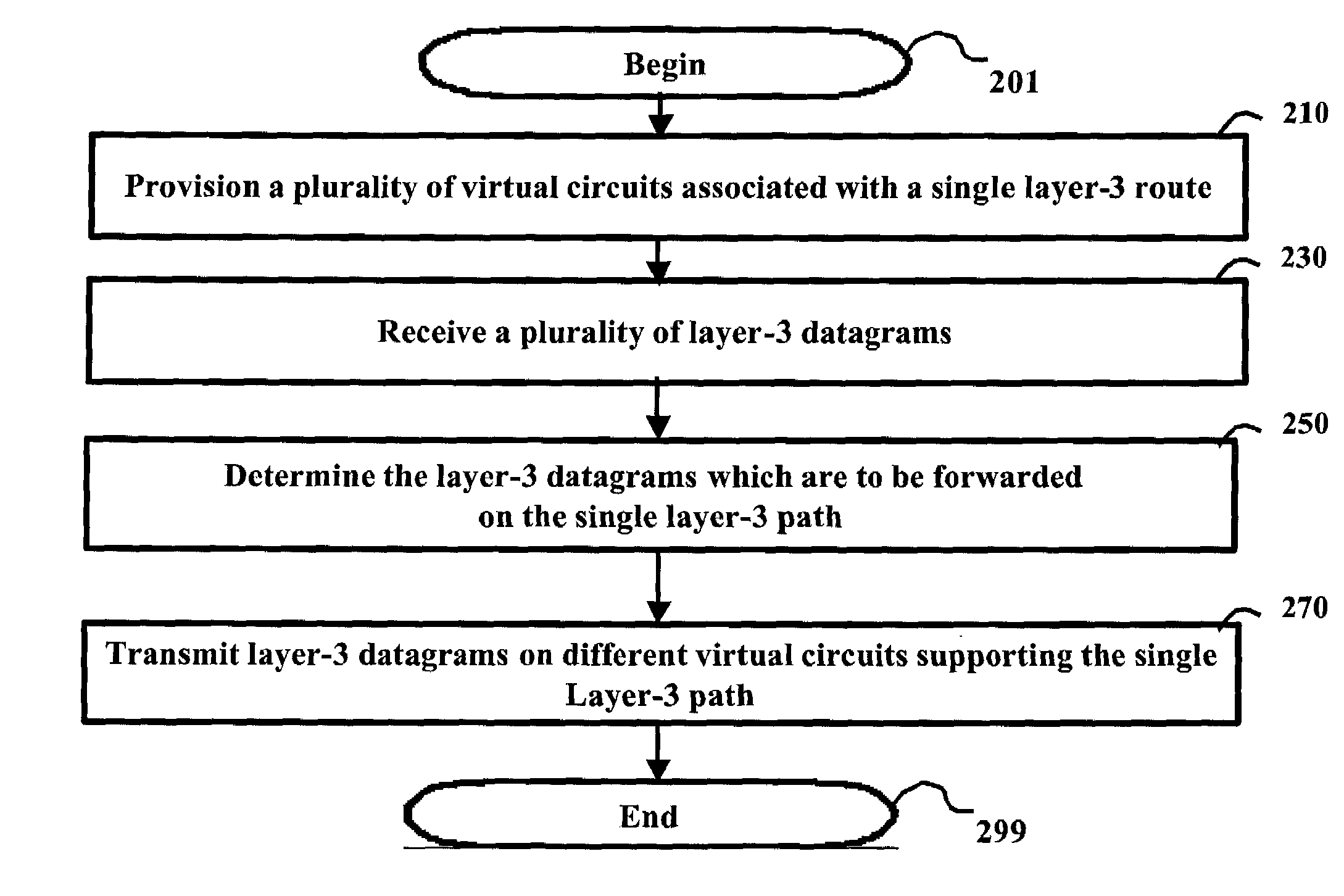
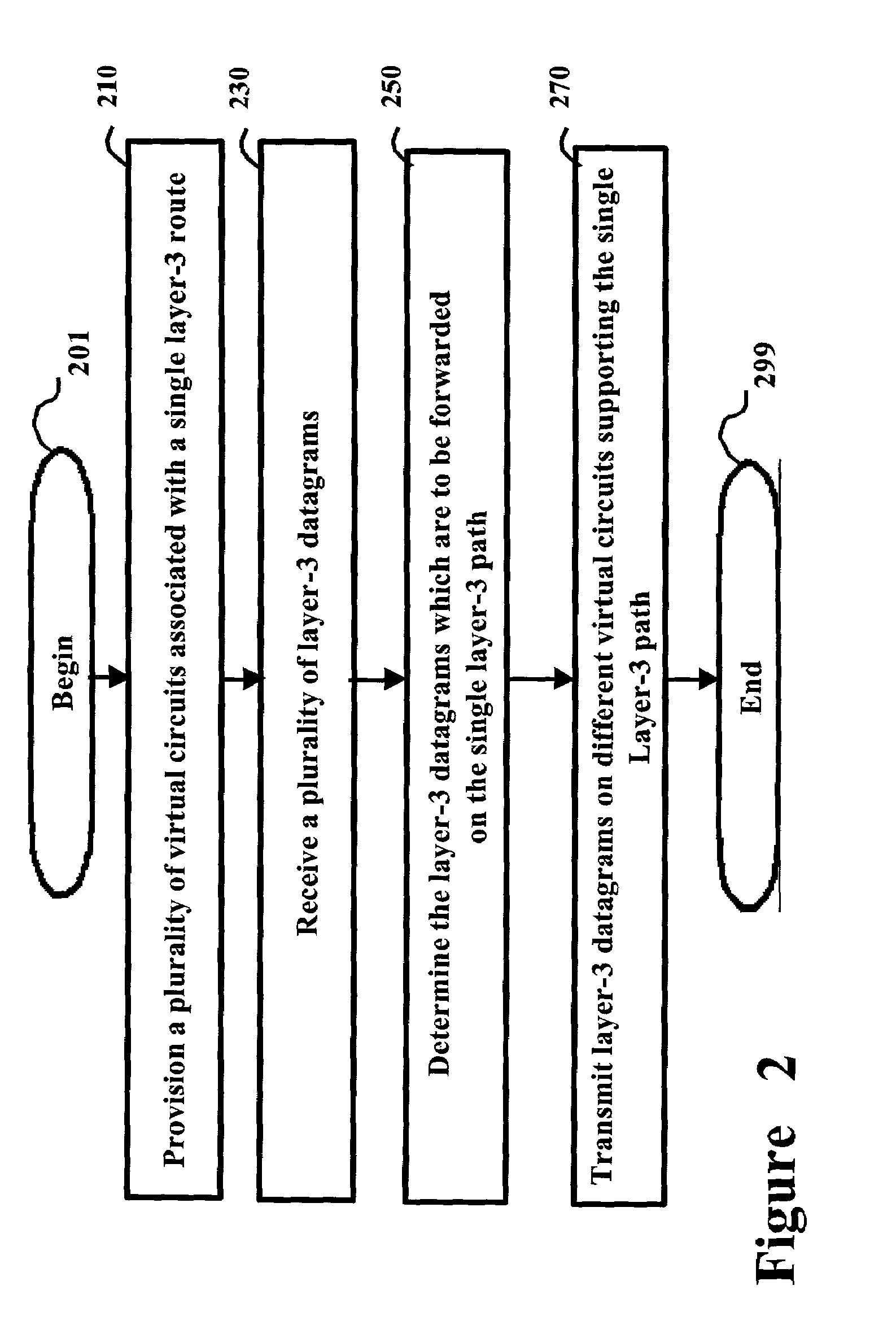
[0022]In accordance with the present invention, multiple layer-2 virtual circuits are associated with single layer-3 route, and the traffic load of the layer-3 route is distributed on the layer-2 virtual circuits. Thus, a high aggregate bandwidth may be available between two layer-3 devices at either end of a layer-3 route. In addition, the solutions may be implemented without adding any (or at least substantial) complexity to the layer-3 routing protocols.

[0023]Several aspects of the invention are described below with reference to example environments for illustration. It should be understood that numerous specific details, relationships, and methods are set forth to provide a full understanding of the invention. One skilled in the relevant art, however, will readily recognize that the invention can be practiced without one or more of the specific details, or with other methods, etc. In other instances, well-known structures or operations ...


PUM


Abstract

An edge router which associates multiple virtual circuits (e.g., PVCs) with an internet protocol (IP) route. The data transfer load on the IP route is distributed on the virtual circuits. As a result, high aggregate effective bandwidth can be provided between edge routers, potentially without having to use a correspondingly high bandwidth physical connections.

Description

BACKGROUND OF THE INVENTION[0001]1. Field of the Invention[0002]The present invention relates to telecommunication networks, and more specifically to a method and apparatus for distributing data transfer load on different paths of a layer-2 network (e.g., ATM) when transporting layer-3 (e.g., Internet Protocol) datagrams.[0003]2. Related Art[0004]Layer-2 networks are often used to transport layer-3 datagrams. In a typical configuration well known in the relevant arts, an edge router interfaces with user systems (e.g., personal computers) and an asynchronous transfer mode (ATM) network to provide data transfers between the two. Another edge router may be present on the other side which provides data transfers between the ATM network and addition systems (e.g., target systems representing servers) accessed by the user systems.[0005]A virtual circuit is often provided on a physical path (of a layer-2 network) to enable data transfers between edge routers. Thus, an edge router encapsula...

Claims


Application Information

Patent Timeline
IPC IPC(8): H04L12/28
CPCH04L12/4633H04L45/24H04L45/10H04L45/04
Inventor SHENOY, SUDHAKARPHADNIS, AMIT S.
Owner CISCO TECH INC
Features
  • R&D
  • Intellectual Property
  • Life Sciences
  • Materials
  • Tech Scout
  • Unparalleled Data Quality
  • Higher Quality Content
  • 60% Fewer Hallucinations
Learn More