
Method and system for modeling and managing terrain, buildings, and infrastructure

a technology for terrain and buildings, applied in the field of engineering and geographical information systems, can solve problems such as inadequacies, interference, and the inability to effectively manage indoor wireless pbx (private branch exchange) systems or wireless local area networks, and achieve the effect of rapid and automated

Active Publication Date: 2007-01-16
EXTREME NETWORKS INC
View PDF120 Cites 394 Cited by
  • Summary
  • Abstract
  • Description
  • Claims
  • Application Information

AI Technical Summary

Benefits of technology

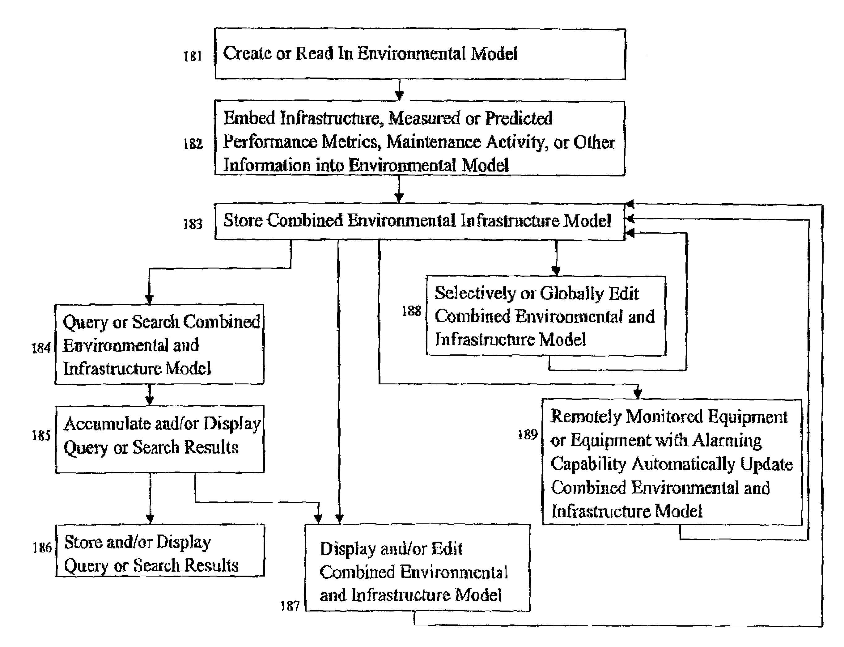
The present invention provides a method and system for generating a highly accurate, three-dimensional digital model of a physical environment, including fluctuating terrain elevation and land-use characteristics, building geometries, positions, and heights, objects located in the vicinity of buildings, and the internal layout of the walls, doors, ceilings, elevators, stairwells, windows, furniture, and equipment located within buildings. This unified method offers a significant value for communications engineers and allows the database model of a distributed network to interact with the actual physical network of components which are so modeled in order to determine performance and alarm events as well as system or network performance metrics that may be compared, stored, measured, visualized, displayed and aggregated to enhance the on-going management of distributed communication networks of an enterprise or global telecommunications carrier. The invention also allows the modeling of different physically distributed networks of communication components within a building or from outside of a building to inside of a building, or within underground tunnels into a building or to the outside environment. The resulting three-dimensional digital model combines all aspects of the physical environment contained within the separate pieces of information utilized and can be used for prediction, analysis, and archival record of a wireless communication system, computer network system, or for civil utilities planning and maintenance purposes.

Problems solved by technology

As wireless communications use increases, radio frequency (RF) coverage within and around buildings and signal penetration into buildings from outside transmitting sources has quickly become an important design issue for wireless engineers who must design and deploy cellular telephone systems, paging systems, or new wireless systems and technologies such as personal communication networks or wireless local area networks.
A common problem for wireless systems is inadequate coverage, or a “dead zone,” in a specific location, such as a conference room.
It is now understood that an indoor wireless PBX (private branch exchange) system or wireless local area network can be rendered useless by interference from nearby, similar systems.
The costs of in-building and microcell devices which provide wireless coverage within a 2 kilometer radius are diminishing, and the workload for RF engineers and technicians to install these on-premises systems is increasing sharply.
However, none of the preceding tools provide an automated means of generating a seamlessly integrated, three-dimensional digital representation of a physical environment that combines terrain, buildings, and the internal structure of the buildings.
In practice, however, many pre-existing building or campus databases are designed only on paper, or are represented as photographs or bitmap images, as a database of parameters defining the environment does not readily exist.
It has been difficult, if not generally impossible, to gather this disparate information and manipulate the data for the purposes of planning and implementation of indoor and outdoor RF wireless communication systems, and each new environment requires tedious manual data formatting in order to run with computer generated wireless prediction models.
ned. They do not, however, teach any type of asset management which combines site-specific environment models with models of the actual installed equipment infrastructure, nor do they provide any information as to the specific format of the digital model of the physical environment or any indication of how the digital model was construc
Furthermore, none of the above cited references contemplate combining three-dimensional digital models of internal building structures with three-dimensional models of outdoor terrain and building geometries into a database format that also includes site-specific component layout information of an actual physical distributed network.
Furthermore, the above cited references do not teach an asset management method or system that allows a site-specific database model to include a site-specific representation of a distributed network of components, such that the actual physical network of components being modeled may also be accounted for, maintained, monitored for performance or alarms, and subsequently managed in an interactive manner on a component-by-component basis or system wide basis using a common database format.
While the above cited patents show the difficulty in obtaining such models for city environments, they do not suggest a systematic, repeatable and fast methodology or algorithmic approach for creating a three-dimensional model of a physical environment that combines both terrain and buildings (or other objects such as trees, natural or man made objects, towers, partitions, walls, and the like) such that the completed representation may be stored and viewed in a vector format that is optimal for the purposes of planning and deploying and tracking maintenance and cost records as well as on-going performance data of wireless communication equipment, computer network equipment, or any form of structured cabling network, or distributed network of components within a model that represents the actual physical environment.

Method used


Image

  • Method and system for modeling and managing terrain, buildings, and infrastructure
  • Method and system for modeling and managing terrain, buildings, and infrastructure
  • Method and system for modeling and managing terrain, buildings, and infrastructure

Examples


Embodiment Construction

[0037]Referring now to the drawings there is shown a method for creating, using, and managing a three-dimensional digital model of the physical environment that combines outdoor terrain elevation and land-use information, building placements, heights, and geometries, and the interior structure of buildings such as walls, floors, windows, and doors. The resulting three-dimensional digital model represents a seamless integration of indoor and outdoor environments.

[0038]In order to perform highly accurate, location-specific simulations of wireless communication system performance, or to maintain site-specific records of equipment cost, installation cost, repair records or equipment replacement or service, or to monitor or track performance data of the network, or to keep an archived record of the site specific location of installed equipment over time and space, a very detailed description of the physical environment in three-dimensions is required. Until recently, high-resolution geog...


PUM


Abstract

A method and system for creating, using, and managing a three-dimensional digital model of the physical environment combines outdoor terrain elevation and land-use information, building placements, heights and geometries of the interior structure of buildings, along with site-specific models of components that are distributed spatially within a physical environment. The present invention separately provides an asset management system that allows the integrated three-dimensional model of the outdoor, indoor, and distributed infrastructure equipment to communicate with and aggregate the information pertaining to actual physical components of the actual network, thereby providing a management system that can track the on-going performance, cost, maintenance history, and depreciation of multiple networks using the site-specific unified digital format.

Description

CROSS-REFERENCE TO RELATED APPLICATIONS[0001]This application claims priority under 35 U.S.C. § 120 to U.S. Provisional Patent Application Ser. No. 60 / 268,360 filed on Feb. 14, 2001.[0002]This application is related to applications Ser. No. 09 / 318,841 now issued as U.S. Pat. No. 6,850,946, entitled “Method And System for a Building Database Manipulator,” filed by T. S. Rappaport and R. R. Skidmore, Ser. No. 09 / 318,842 now issued as U.S. Pat. No. 6,493,679, entitled “Method and System for Managing a Real Time Bill of Materials,” filed by T. S. Rappaport and R. R. Skidmore, Ser. No. 09 / 318,840 now issued as U.S. Pat. No. 6,317,599, entitled “Method and System For Automated Optimization of Communication component Position in 3D” filed by T. S. Rappaport and R. R. Skidmore, Ser. No. 09 / 633,122 now issued as U.S. Pat. No. 7,096,173, entitled “Method and System for Designing or Deploying a Communications Network which Allows Simultaneous Selection of Multiple Components” fled by T. S. Rap...

Claims


Application Information

Patent Timeline
Patent Type & Authority Patents(United States)
IPC IPC(8): H04H1/00H04Q7/20G06F17/50G06Q10/10H04H20/00H04W16/20
CPCH04W16/20G06Q10/10
Inventor RAPPAPORT, THEODORE S.SKIDMORE, ROGER R.SHEETHALNATH, PRAVEEN
Owner EXTREME NETWORKS INC
Learn More