Looper for tufting machine

a looper and looping machine technology, applied in the field of loopers, can solve the problems of large amount of yarn material waste, damage to backing cloth and carpet, and difficulty in uniform cutting of loops with conventional loopers with flat edges, so as to achieve smooth cutting of yarns, reliable and precise cutting

Active Publication Date: 2007-01-23
NARA +1
View PDF7 Cites 6 Cited by
  • Summary
  • Abstract
  • Description
  • Claims
  • Application Information

AI Technical Summary

Benefits of technology

[0005]With this arrangement, the corrugations formed along the bottom edge of the hook throat portion will provide suitable resistance to loop piles hooked by the hook throat portion, thereby preventing the loop piles from sliding away from the knife and being held in an unexpected position of the hook throat portion. This makes it possible to form loop piles having uniform lengths. The loop piles can be reliably and precisely cut at constant positions. Thus, by using the looper according to the present invention, it is possible to smoothly cut yarns which have been difficult to cut, such as single yarns having a large denier, monofilaments, filaments, tape yarns and natural fibers like cotton.

Problems solved by technology

Such loops will be either cut again at different positions of a cutting edge or simply torn and will damage the backing cloth and carpet.
A large amount of yarn material is thus wasted.
If pile yarns are made of a material having no remaining elongation or a markedly low remaining elongation compared to ordinary tufting yarn, such as yarns for artificial turf, natural fiber yarns, and thick monofilaments, it is especially difficult to cut loops uniformly with conventional loopers having flat edges.
Thus, large amounts of defective carpets tend to be produced.
In a worst case, tufting is simply impossible.

Method used


Image

  • Looper for tufting machine
  • Looper for tufting machine
  • Looper for tufting machine

Examples


Embodiment Construction

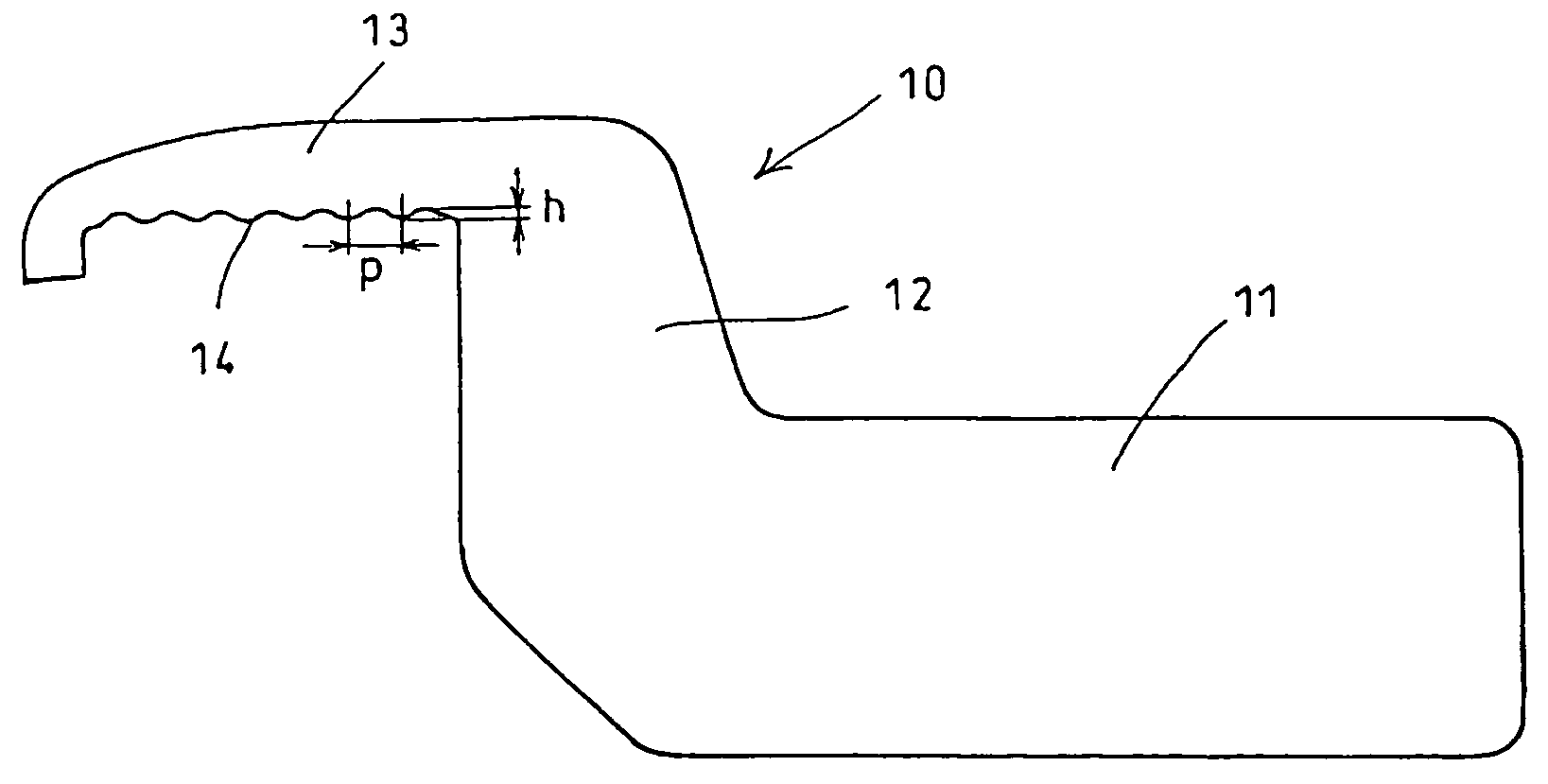
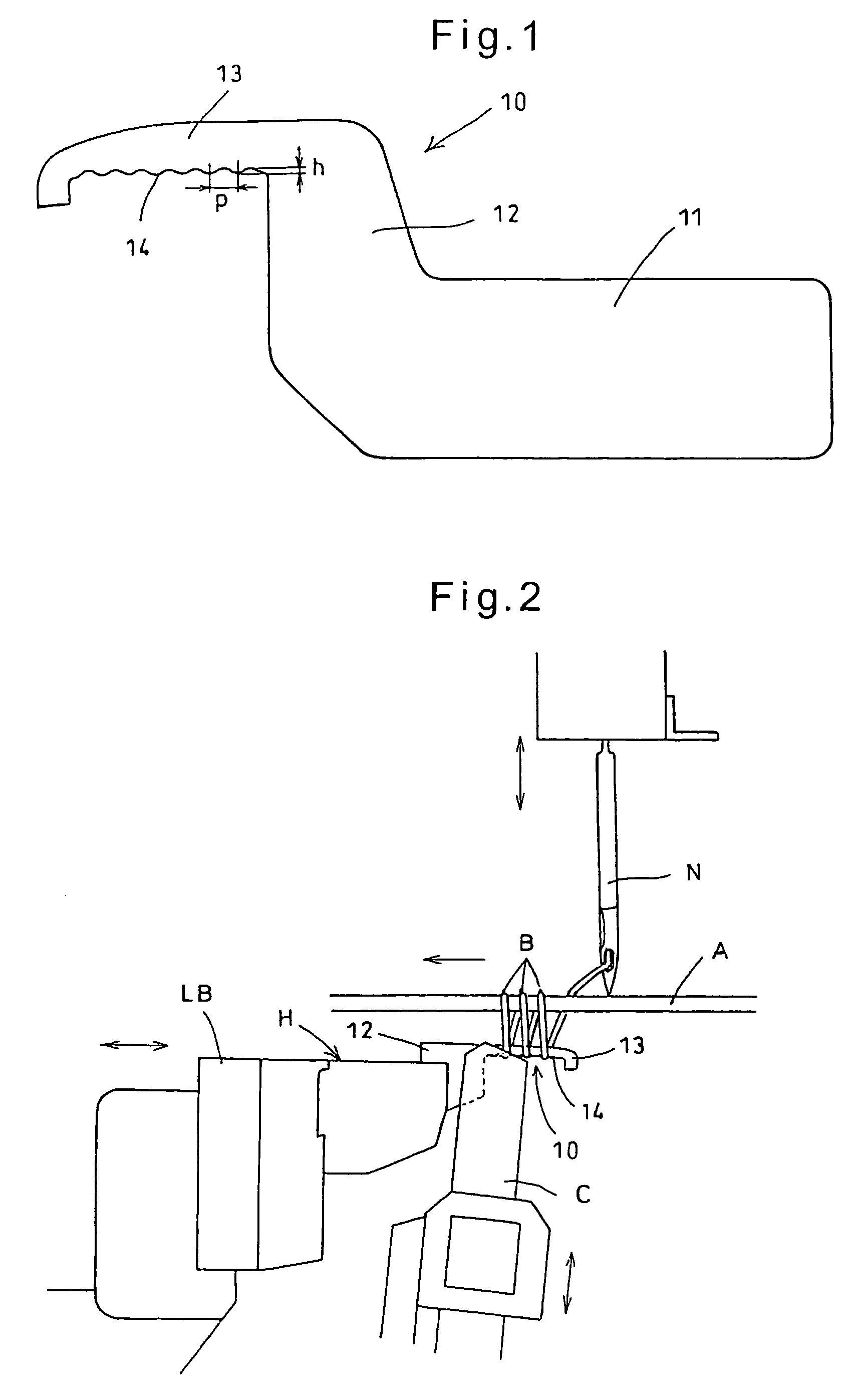
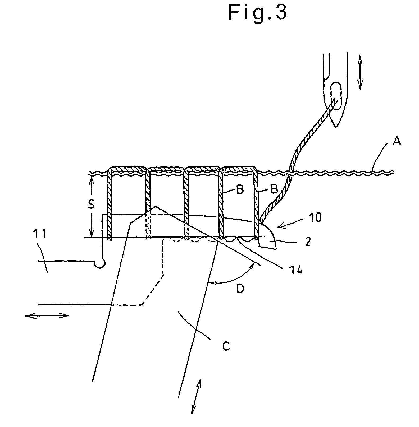
[0014]Now an embodiment of the present invention is described with reference to FIGS. 1 to 5. As shown in FIG. 1, a looper 10 according to the present invention comprises a base portion 11 supported on a looper block, which is described later, a neck portion 12 extending substantially vertically upwardly from the base portion 11, and a hook throat portion 13 extending substantially horizontally from the neck portion 12 and having a bottom edge 14 which is formed with corrugations along an entire length thereof or partly along the length thereof. The corrugations are typically formed with equal pitches p and heights h. But the corrugations may be formed such that their pitches and / or heights decrease gradually toward a tip of the hook throat portion 13. Preferably, the corrugations have heights h in the range of about 0.01 to 2 mm, more preferably in the range of about 0.1 to 2 mm, and pitches p in the range of about 0.01 to 6 mm, more preferably in the range of about 0.1 to 6 mm.

[00...


PUM


Abstract

A looper for use in a tufting machine includes a hook throat portion having a bottom edge. Corrugations are formed along the bottom edge. The corrugations provide suitable resistance to loop piles hooked by the hook throat portion, thereby preventing the loop piles from being held in an unexpected position of the hook throat portion. This makes it possible to form loop piles of uniform lengths on carpets. Also, the corrugations will prevent the loop piles from sliding away from a knife so that the loop piles can be reliably, precisely and cleanly cut at constant positions.

Description

BACKGROUND OF THE INVENTION[0001]The present invention relates to a looper for use in a tufting machine for manufacturing carpets.[0002]FIG. 6 shows a conventional looper 1 which includes a hook throat portion 2 having a bottom edge 3. Loops B are formed on a backing cloth A by moving the looper 1 back and forth as shown by arrows while feeding the backing cloth A in a direction of an arrow. Since the bottom edge 3 is a straight and smooth ground surface, when the backing cloth A and the looper 1 move, tips of the loops B slide along the bottom edge 3 toward an opposite end to a tip of the hook throat portion 2 as shown. When the loops B are cut by knife C, the loops B tend to be pushed by the knife C toward a front corner of the hook throat portion 2 because the knife C has a shear angle D. Some of such loops may not be cut at all or partly cut. Such loops will be either cut again at different positions of a cutting edge or simply torn and will damage the backing cloth and carpet. ...

Claims


Application Information

Patent Timeline
Patent Type & Authority Patents(United States)
IPC IPC(8): D05C15/22D05C15/24
CPCD05C15/24D05C15/22
Inventor YOSHINO, SOTA
Owner NARA
Why Eureka
Try Eureka