
Heart valve repair apparatus and methods

a heart valve and apparatus technology, applied in the field of repair and replacement of heart valves, can solve the problems of chords bursting, small safety margin, constant change of the attachment distance of leaflet edges, etc., and achieve the effects of improving the function of left ventricular, preventing bulging of the posterior wall of the heart, and being reliable and permanen

Inactive Publication Date: 2007-01-23
CARDIAC VALVE TECH
View PDF61 Cites 213 Cited by
  • Summary
  • Abstract
  • Description
  • Claims
  • Application Information

AI Technical Summary

Benefits of technology

"The invention provides a device for supporting a heart valve in a patient with a degenerated valve. The device includes a support member attached to the valve and a post extending from the support member. The post can be fixed to the valve annulus or to the leaflets of the valve. The device can be easily attached to the valve and can be adjusted to ensure proper coaptation of the valve leaflets. The invention can be used in repairing or replacing heart valves and can be made from biocompatible materials. The device can also be used to correct ischemic conditions by modifying the shape of the valve annulus."

Problems solved by technology

Typically, the contact surface is about 12 mm in a direction perpendicular to the anterior-posterior direction and this provides little margin of safety.
Unfortunately, this anchor point (i.e., the inner wall of the left ventricle) must move with each heartbeat and so the distance between the attachment of the leaflet edges is constantly changing.
Chords may also rupture.
This valve was not suitable for any type of plastic procedure and, accordingly, numerous valve prostheses were developed to replace the entire valve, i.e., the annulus, leaflets and chords.
Recently, it has become apparent that combinations of these two problems are relatively common.
Unfortunately, despite the fact that the leaflet tissue is suitable for retention, mitral repair is performed for less than half of the cases where mitral regurgitation is the problem.
One main problem is that mitral valve repair technology has not kept pace with the change in mitral valve pathology.
Few surgeons or surgical centers are equipped for or capable of performing this type of work on a routine basis.
These rings may appear to be a solution for a variety of problems but are not ideal for many ischemic and degenerative disease conditions.
Despite many attempts, the homograft mitral valve replacement is not an operation which can be performed reliably.
Failures occur because of the unreliability of attachment of the chords to the left ventricle.
However, it is virtually impossible to ensure that the chords are correctly spaced inside the ventricle to produce a competent valve.
Again, the inner surface of the ventricle is a moving surface and it is almost impossible to guarantee that a chord extending from a leaflet edge will be fixed in such a way that the anterior and posterior leaflets are reliably aligned during valve operation.
Various other repair procedures are performed, but these are limited to the removal of leaflet tissue which is poorly supported and to chordal shortening and replacement.
Many valves simply remain unrepaired due to the shortage of acceptable techniques and apparatus.
Despite numerous attempts to produce durable leaflet replacements, none have been found.
The cost of demonstrating the value of a new material is extremely high.
Regulatory issues in this field are the single most expensive factor.
To date, this remains a troublesome variable to the valve repair.
However, the regurgitation often becomes severe after left ventricular ischemia occurs.
This often leaves a degree of mitral regurgitation and mitral stenosis results.

Method used


Image

  • Heart valve repair apparatus and methods
  • Heart valve repair apparatus and methods
  • Heart valve repair apparatus and methods

Examples


Embodiment Construction

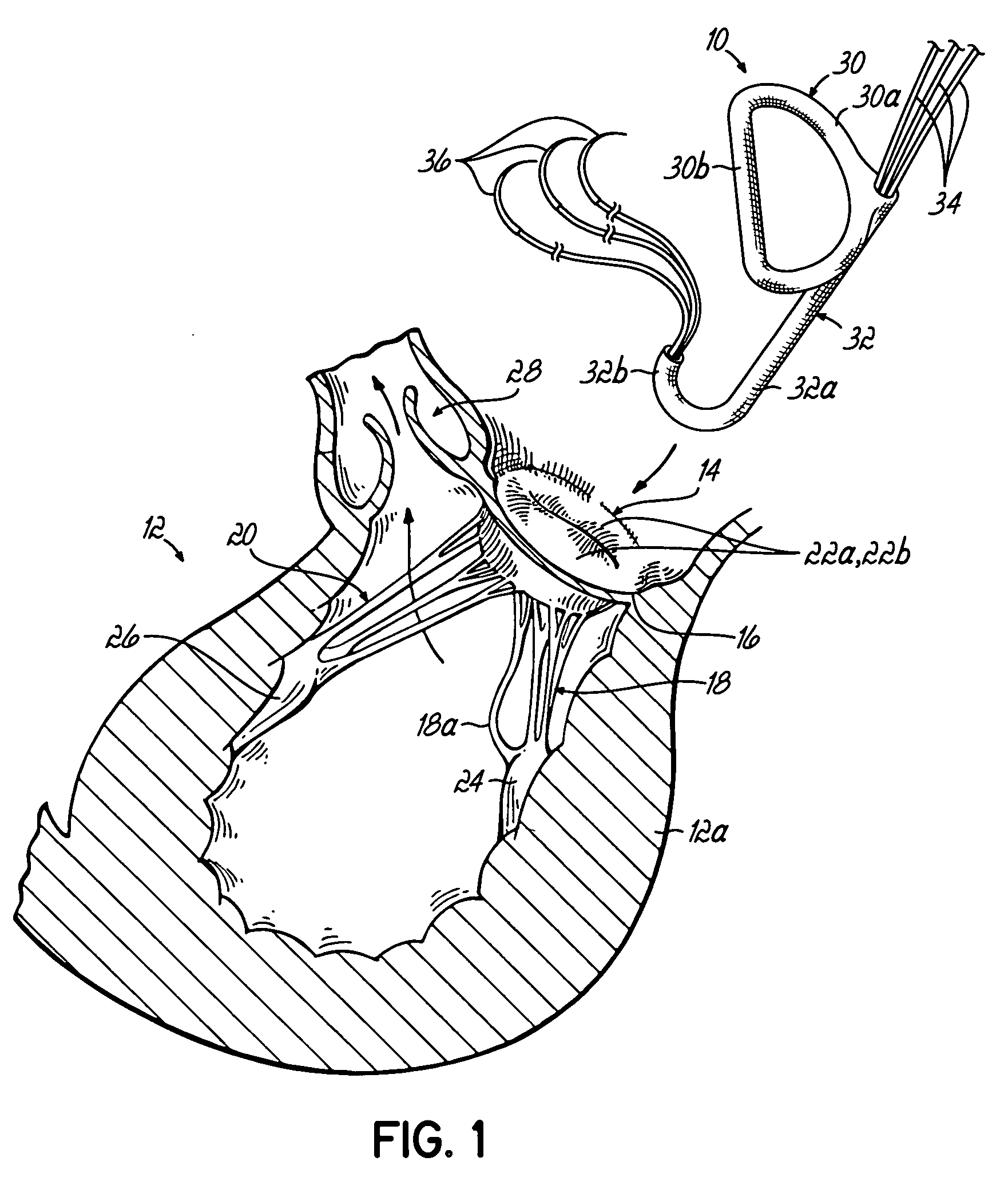
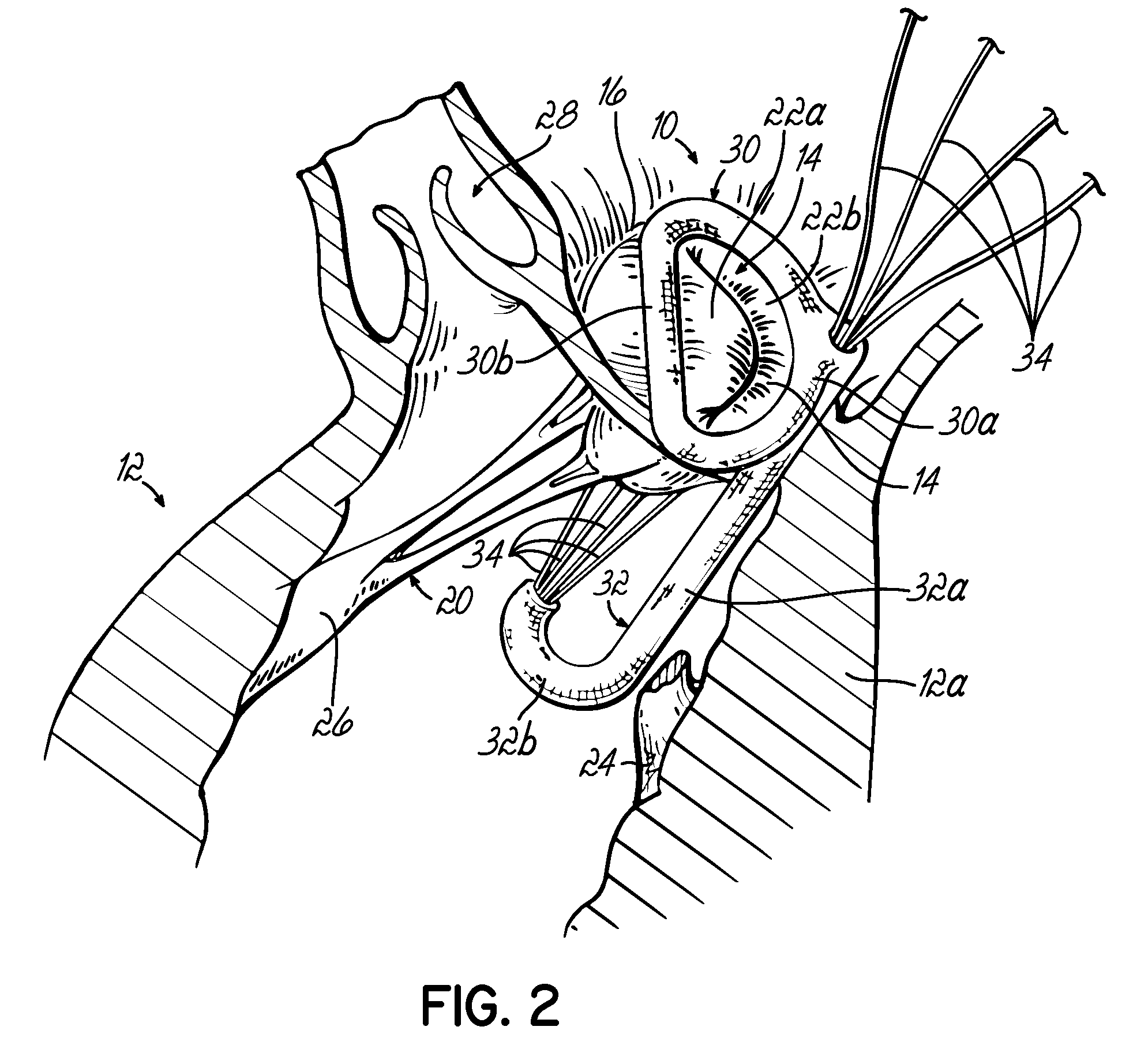
[0054]Referring first to FIG. 1, a device 10 for supporting a heart valve in a patient is shown. In the illustrated example, the left ventricle 12 of a patient's heart is shown in cross section with a mitral valve 14 for supplying blood into the ventricle 12. Mitral valve 14 includes an annulus 16 generally lying in a plane and a plurality of native chordae tendonae or chords 18, 20 respectively connected with a pair of valve leaflets 22a, 22b at one end and papillary muscles 24, 26 at an opposite end. In a normally functioning heart, chords 18, 20 support the anterior valve leaflet 22a and posterior valve leaflet 22b between open (diastolic) and closed (systolic) positions to selectively allow and prevent blood flow into and out of left ventricle 12. Blood enters left ventricle 12 through mitral valve 14 and is expelled during the subsequent contraction of the heart muscle through aortic valve 28. It will be appreciated that the present invention is applicable to heart valves other...


PUM


Abstract

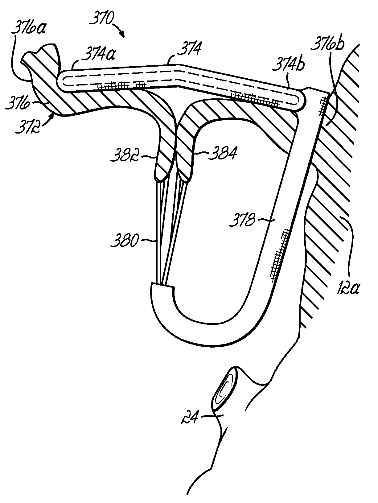
Valve repair apparatus and methods for ensuring proper coaptation and operation of the leaflets of a heart valve. Main aspects of the disclosure relate to devices including a support member configured for attachment to the heart valve annulus, a post extending from the support member away from the plane of the annulus and a connector coupled with the post and configured for attachment to at least one of the leaflets. The various embodiments may include a replacement heart valve connected with the support member for facilitating full replacement as opposed to near repair of an existing native heart valve. Various other devices include support structure and one or more posts connected to opposite sides of the support structure and extending from one side of the valve annulus to another to modify the shape of the annulus.

Description

[0001]This application is a divisional of application Ser. No. 10 / 268,028 filed Oct. 9, 2002 now U.S. Pat. No. 6,797,002 which is a divisional of application Ser. No. 09 / 496,450 filed Feb. 2, 2000 (now abandoned), the disclosures of which are fully incorporated herein by reference.FIELD OF THE INVENTION[0002]The present invention generally relates to heart valve repair and replacement techniques and apparatus. More specifically, the invention relates to the repair of heart valves having various malformations and dysfunctions.BACKGROUND OF THE INVENTION[0003]The mitral valve depends on adequate apposition or alignment between the anterior and posterior leaflets along a relatively long surface area under high pressure conditions. Typically, the contact surface is about 12 mm in a direction perpendicular to the anterior-posterior direction and this provides little margin of safety. The leaflet margins are attached to numerous fine chords suspended from attachment points along the inner...

Claims


Application Information

Patent Timeline
Patent Type & Authority Patents(United States)
IPC IPC(8): A61F2/24
CPCA61F2/2412A61F2/2418A61F2/2445A61F2/2454A61F2/2457A61F2/2448A61F2220/0091A61F2/2466
Inventor SPENCE, PAUL A.ORTIZ, MARK
Owner CARDIAC VALVE TECH
Learn More