Heart valve repair apparatus and methods

a heart valve and apparatus technology, applied in the field of repair and replacement of heart valves, can solve the problems of chords bursting, the distance between the attachment of leaflet edges is constantly changing, and the safety margin is small, so as to improve the function of the left ventricular wall, prevent the bulging of the posterior wall of the heart, and be reliable and permanent.

a heart valve and apparatus technology, applied in the field of repair and replacement of heart valves, can solve the problems of chords bursting, the distance between the attachment of leaflet edges is constantly changing, and the safety margin is small, so as to improve the function of the left ventricular wall, prevent the bulging of the posterior wall of the heart, and be reliable and permanent.

US20070050020A1Inactive Publication Date: 2007-03-01CARDIAC VALVE TECH

Image

  • Heart valve repair apparatus and methods
  • Heart valve repair apparatus and methods
  • Heart valve repair apparatus and methods

Examples


Embodiment Construction

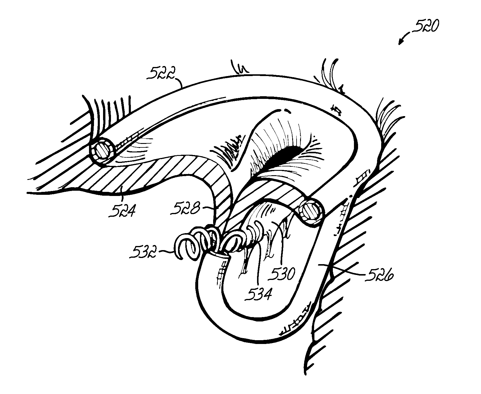
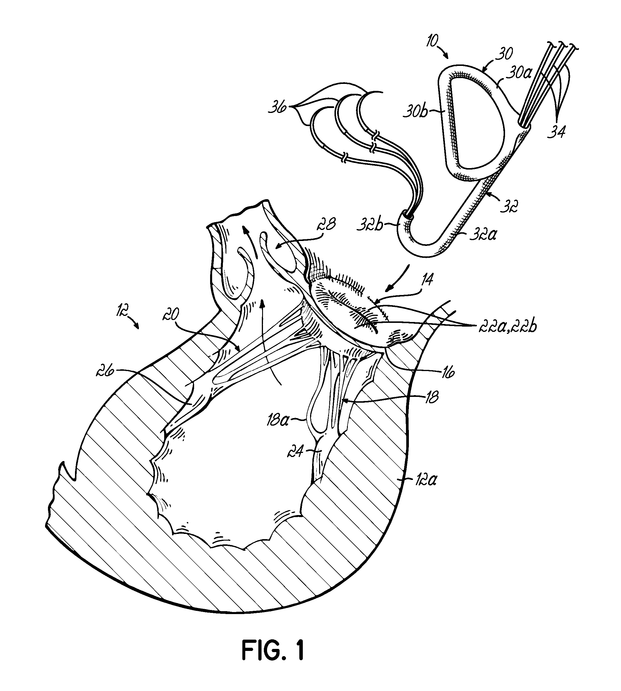
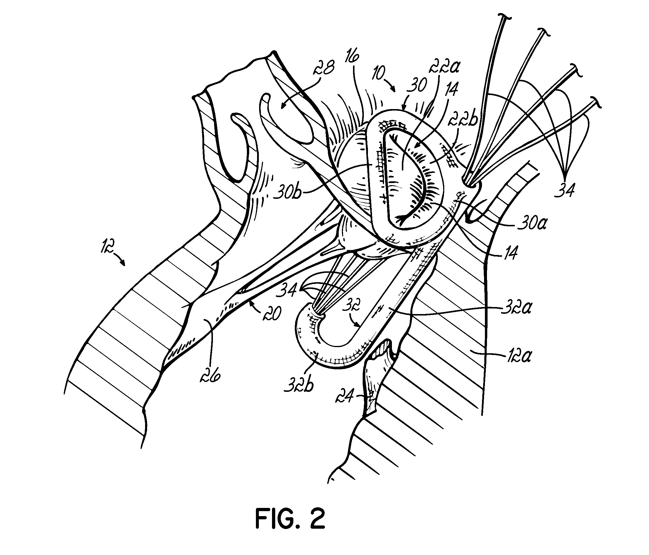
[0054] Referring first to FIG. 1, a device 10 for supporting a heart valve in a patient is shown. In the illustrated example, the left ventricle 12 of a patient's heart is shown in cross section with a mitral valve 14 for supplying blood into the ventricle 12. Mitral valve 14 includes an annulus 16 generally lying in a plane and a plurality of native chordae tendonae or chords 18, 20 respectively connected with a pair of valve leaflets 22a, 22b at one end and papillary muscles 24, 26 at an opposite end. In a normally functioning heart, chords 18, 20 support the anterior valve leaflet 22a and posterior valve leaflet 22b between open (diastolic) and closed (systolic) positions to selectively allow and prevent blood flow into and out of left ventricle 12. Blood enters left ventricle 12 through mitral valve 14 and is expelled during the subsequent contraction of the heart muscle through aortic valve 28. It will be appreciated that the present invention is applicable to heart valves othe...


PUM


Abstract

Valve repair apparatus and methods for ensuring proper coaptation and operation of the leaflets of a heart valve. Main aspects of the disclosure relate to devices including a support member configured for attachment to the heart valve annulus, a post extending from the support member away from the plane of the annulus and a connector coupled with the post and configured for attachment to at least one of the leaflets. The various embodiments may include a replacement heart valve connected with the support member for facilitating full replacement as opposed to near repair of an existing native heart valve. Various other devices include support structure and one or more posts connected to opposite sides of the support structure and extending from one side of the valve annulus to another to modify the shape of the annulus.

Description

[0001] This application is a divisional of application Ser. No. 10 / 695,380, filed Oct. 28, 2003 (pending) which is a divisional of application Ser. No. 10 / 268,028 filed Oct. 9, 2002 (now U.S. Pat. No. 6,797,002) which is a continuation of application Ser. No. 09 / 496,450 filed Feb. 2, 2000 (now abandoned), the disclosures of which are fully incorporated herein by reference.FIELD OF THE INVENTION [0002] The present invention generally relates to heart valve repair and replacement techniques and apparatus. More specifically, the invention relates to the repair of heart valves having various malformations and dysfunctions. BACKGROUND OF THE INVENTION [0003] The mitral valve depends on adequate apposition or alignment between the anterior and posterior leaflets along a relatively long surface area under high pressure conditions. Typically, the contact surface is about 12 mm in a direction perpendicular to the anterior-posterior direction and this provides little margin of safety. The lea...

Claims


Application Information

Patent Timeline
01 Mar 2007
Publication
US20070050020A1
IPC
A61F2/24
CPC
A61F2/2412; A61F2/2418; A61F2/2445; A61F2220/0091; A61F2/2454; A61F2/2457; A61F2/2466; A61F2/2448
Inventors
SPENCE, PAUL A.