Automation-optimized microarray package

a microarray and automatic optimization technology, applied in the field of microarrays, can solve the problems of plastic packaging generally insufficient mechanically stable to allow, reactive surface production, glass-to-plastic bond failure,

Inactive Publication Date: 2007-01-23
AGILENT TECH INC
View PDF10 Cites 50 Cited by
  • Summary
  • Abstract
  • Description
  • Claims
  • Application Information

AI Technical Summary

Benefits of technology

[0016]One embodiment of the present invention is a linear pocket strip comprising a series of pockets, or cells, into each pocket of which a microarray can be positioned. The pockets, and microarrays contained within the pockets, are covered by a cover strip that can be heat sealed to the first plastic strip so that each microarray is positioned within a tightly sealed reaction chamber formed by bonding the cover strip to the pocket strip, the resulting linear series of reaction chambers called a “microarray strip.” Membrane septa can be affixed to, or embedded within, the cover strip to provide resealable ports through which sample solutions or gasses can be introduced into each reaction chamber. The microarray strip may include one or more linear sequences of regularly-spaced tractor feed perforations, or other features that can be au

Problems solved by technology

Unfortunately, many sealants used to seal glass to plastic may contain unreactive monomer or produce reactive surfaces that interfere chemically within the hybridization processes that need to be carried out within the reaction vessel.
A second disadvantage is that glass and plastic exhibit different thermal expansion behaviors, creating high stress that may lead to glass-to-plastic bond failures during exposure of the plastic microarray packaging and embedded microarray to thermal fluctuations.
A third disadvantage of the plastic packaging shown in FIG. 1 is that the plastic packaging is generally insufficiently mechanically stable to allow for reliable automated positioning of the microarray within a scanning device.
A fourth disadvantage of the plastic packaging shown in FIG. 1 is that, when the embedded microarray is scanned without removing the microarray from the plastic packaging,

Method used


Image

  • Automation-optimized microarray package
  • Automation-optimized microarray package
  • Automation-optimized microarray package

Examples


Embodiment Construction

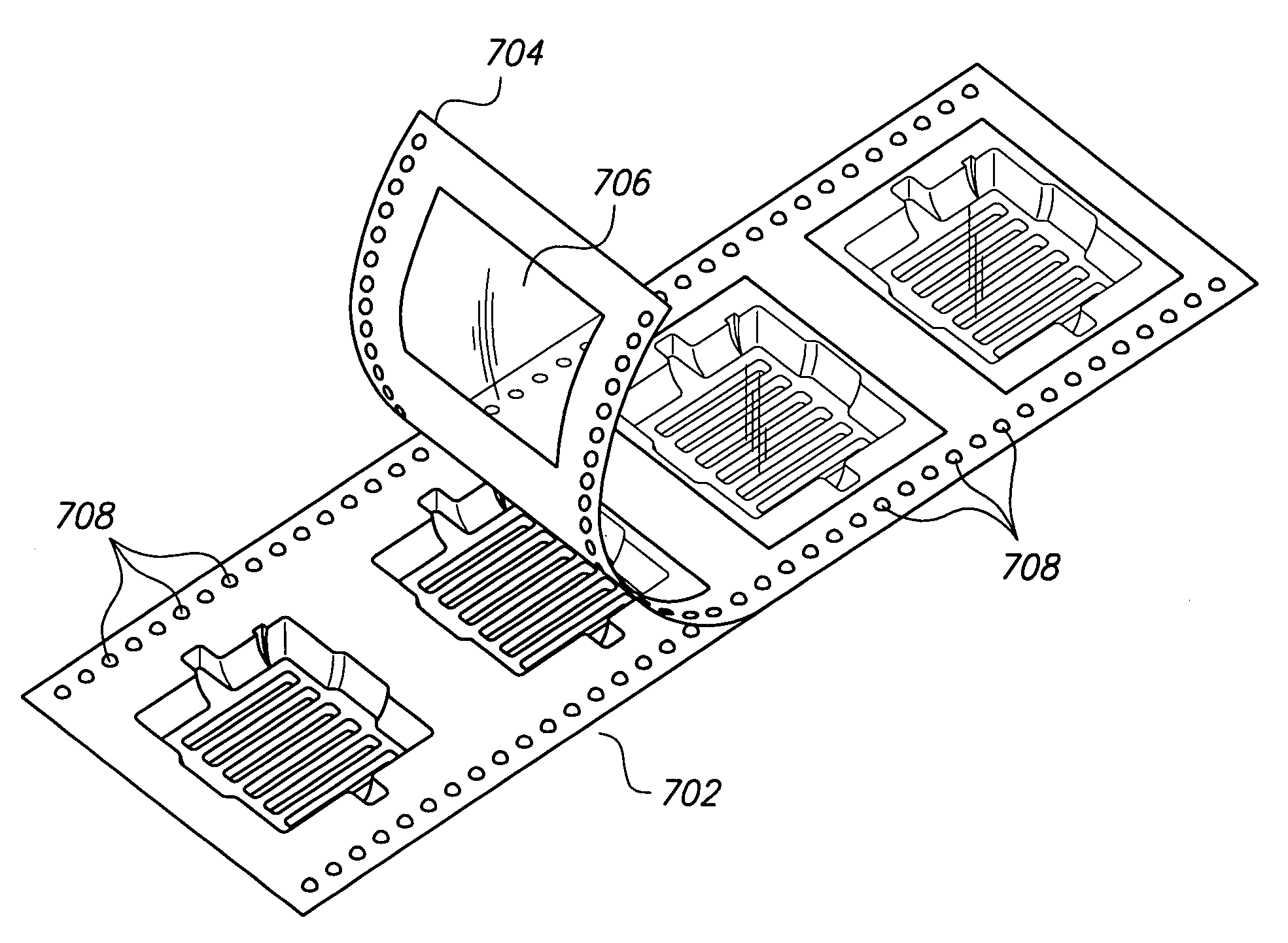
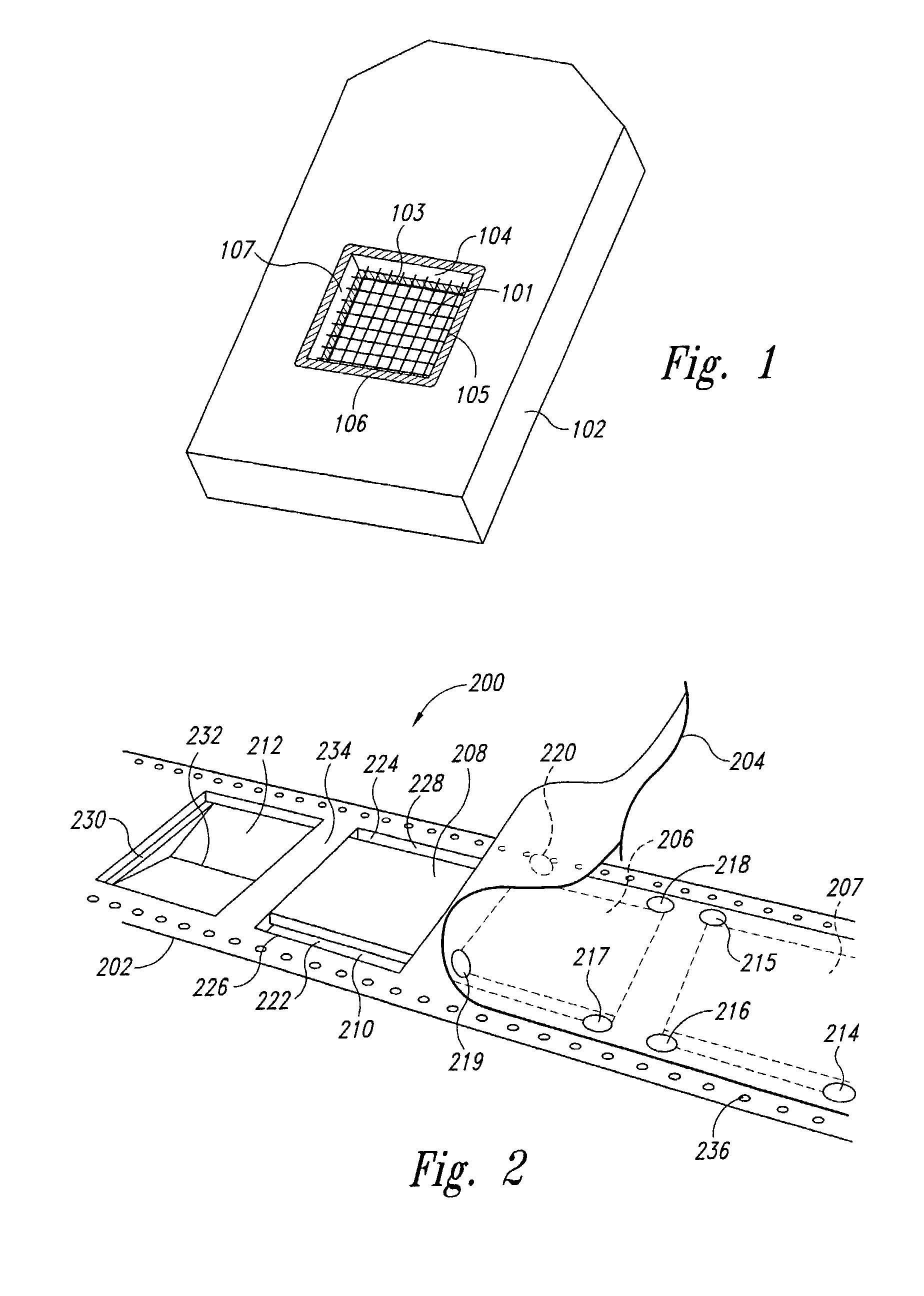
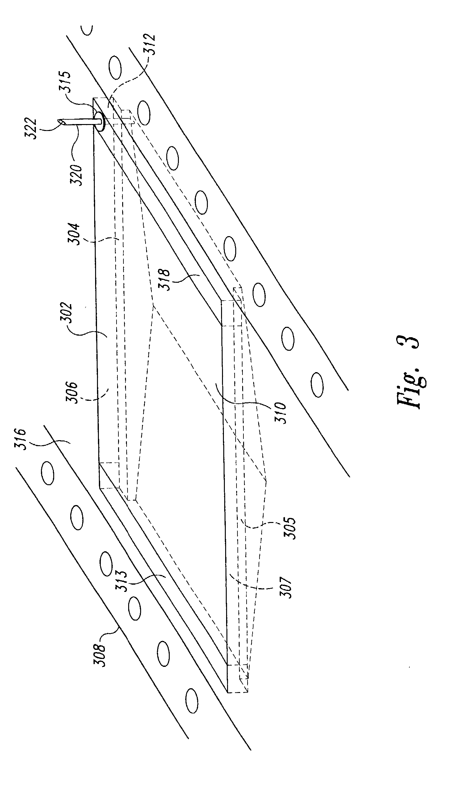
[0024]One embodiment of the present invention is a linear sequence of regularly-spaced, tightly sealed microreaction chambers that each contains a precisely positioned and oriented microarray, called a “microarray strip.” The microarray strip further includes tractor feed perforations or other regularly spaced mechanical or optical features that allow the microarray strip, and the microarray contained within the microarray strip, to be mechanically translated and precisely positioned within various automated electromechanical systems. A microarray strip may also serve as a sequence of economical and reliable storage chambers and as packaging for storing, handling, and transporting microarrays contained within the microarray strip. The microarray strip may be rolled onto reels for compact and reliable storage of microarrays.

[0025]Note that a microarray strip may have a length to width ratio of at least 5 / 1, 10 / 1, 50 / 1, 200 / 1, 500 / 1, or even at least 1000 / 1. Microarray strips may have...


PUM

PropertyMeasurementUnit
Flexibilityaaaaaaaaaa
Mechanical forceaaaaaaaaaa

Abstract

A method and system for economically packaging microarrays into sealed reaction chambers and storage vessels. A pocket strip is manufactured as a linear sequence of pockets, or wells, into which microarrays are positioned. A cover strip is then heat sealed to the upper surface of the pocket strip to create a linear sequence of sealed reaction chambers or storage vessels, each containing a microarray. Mechanical features or optical features are included along the length of the pocket strip to facilitate mechanical translation and positioning of microarrays embedded within the microarray strip. Septa are affixed to, or embedded within, the cover strip to provide resealable ports through which solutions can be introduced into, or extracted from, the reaction chambers. In an alternate embodiment, the microarrays are deposited directly onto the cover strip, eliminating the need for separate microarray substrates.

Description

CROSS-REFERENCE TO RELATED APPLICATION[0001]This application is a continuation-in-part of U.S. application Ser. No. 09 / 775,375, filed Jan. 31, 2001, now pending.TECHNICAL FIELD[0002]The present invention relates to microarrays, also called molecular arrays and biochips, and relates, in particular, to a method and system for packaging microarrays economically, securely, efficiently, and in a way that facilitates automated processing and scanning.BACKGROUND OF THE INVENTION[0003]Microarrays are widely used and increasingly important tools for rapid hybridization analysis of sample solutions against hundreds or thousands of precisely ordered and positioned features on the active surfaces of microarrays that contain different types of molecules. Microarrays are normally prepared by synthesizing or attaching a large number of molecular species to a chemically prepared substrate such as silicone, glass, or plastic. Each feature, or element, on the active surface of the microarray is defin...

Claims


Application Information

Patent Timeline
IPC IPC(8): B01L3/00B01L9/00
CPCB65D75/327B01L3/50853B01L9/52B01J2219/00527B01J2219/00529B01J2219/00585B01J2219/00596B01J2219/00659B01L2300/0822B01J2219/00605
Inventor BASS, JAY K.MCENTEE, JOHN F.
Owner AGILENT TECH INC
Why Eureka
Try Eureka