Circuits, architectures, systems and methods for overvoltage protection

a technology of circuits and circuits, applied in the direction of logic circuit coupling/interface arrangement, pulse technique, electronic switching, etc., can solve the problems of degrading the high-speed performance and capabilities of circuits, ics can suffer significant damage (and sometimes fatalities), and achieve the effect of a level of overvoltage protection

Inactive Publication Date: 2007-01-23
MARVELL INT LTD
View PDF10 Cites 6 Cited by
  • Summary
  • Abstract
  • Description
  • Claims
  • Application Information

AI Technical Summary

Benefits of technology

[0009]The present invention advantageously provides a level of overvoltage protection that is adequate for nearly all applications in which conventional CMOS circuitry can be used, while at the same time, having very little, if any, adverse effect on the speed with which differential data signals may be transmitted on differential signal transmission lines to which the invention is applied.

Problems solved by technology

For example, when such a human handler inadvertently touches the leads of an IC and passes such a high static charge to an input buffer on the IC, significant (and sometimes fatal) damage can be done to the IC if the IC is without some kind of protection against such overvoltages.
These additional parasitic capacitances further degrade the high-speed performance and capabilities of circuit 50, relative to circuit 10.

Method used


Image

  • Circuits, architectures, systems and methods for overvoltage protection
  • Circuits, architectures, systems and methods for overvoltage protection
  • Circuits, architectures, systems and methods for overvoltage protection

Examples


Embodiment Construction

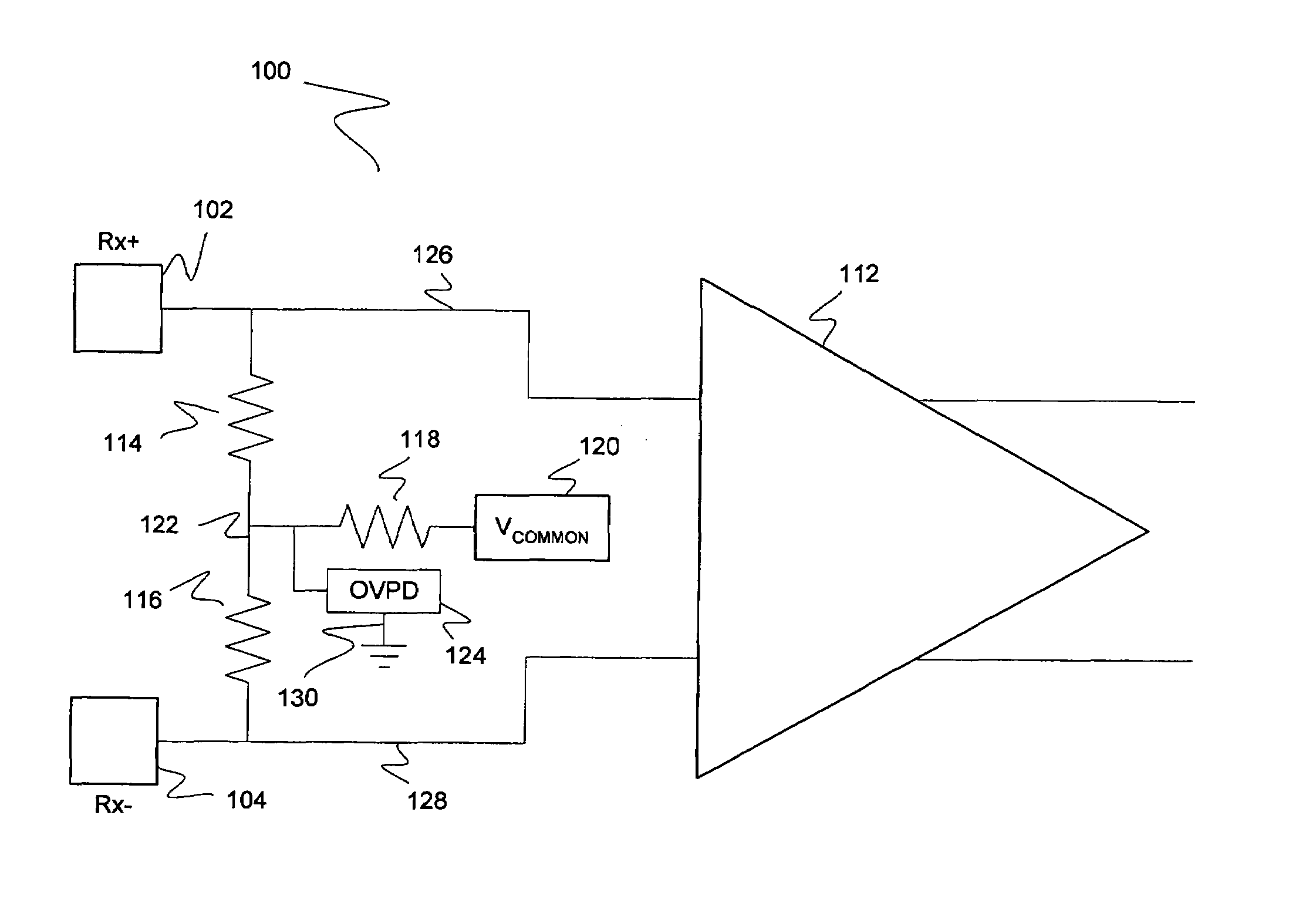
[0016]Reference will now be made in detail to the preferred embodiments of the invention, examples of which are illustrated in the accompanying drawings. While the invention will be described in conjunction with the preferred embodiments, it will be understood that they are not intended to limit the invention to these embodiments. On, the contrary, the invention is intended to cover alternatives, modifications and equivalents, which may be included within the spirit and scope of the invention as defined by the appended claims. Furthermore, in the following detailed description of the present invention, numerous specific details are set forth in order to provide a thorough understanding of the present invention. However, it will be readily apparent to one skilled in the art that the present invention may be practiced without these specific details. In other instances, well-known methods, procedures, components, and circuits have not been described in detail so as not to unnecessarily...


PUM


Abstract

Circuits, architectures, a system and methods for protecting against overvoltages in a high-speed differential signal or circuit. The circuit generally includes (a) a differential signal transmission line, (b) a common mode circuit coupled to and configured to reduce a swing of the differential signal transmission line, and (c) an overvoltage protection circuit coupled to the common mode circuit, wherein the common mode circuit is electrically interposed between the overvoltage protection circuit and the differential signal transmission line. The architectures and / or systems generally include an integrated circuit that embodies one or more of the inventive concepts disclosed herein. The method generally includes shunting the overvoltage to a ground potential through the termination circuit when the differential circuit receives the overvoltage, but otherwise processing the differential signal through circuitry coupled to the differential circuit. The present invention advantageously provides a satisfactory level of overvoltage protection for nearly all applications in which conventional CMOS circuitry can be used, while at the same time, having very little, if any, adverse effect on differential data signal transmission speed.

Description

RELATED APPLICATIONS[0001]This application is a continuation of U.S. application No. 10 / 606,907 filed Jun. 26, 2003, is now a U.S. Pat. No. 7,026,839.FIELD OF THE INVENTION[0002]The present invention generally relates to the field of overvoltage protection. More specifically, embodiments of the present invention pertain to circuitry, architectures, and methods for protecting against transient and direct current (DC) overvoltages in a device receiving a high-speed differential analog signal.DISCUSSION OF THE BACKGROUND[0003]FIG. 1 shows a conventional high-speed differential analog circuit 10. Differential circuit 10 includes differential input terminals Rx+ and Rx−, input buffer 12, termination resistors 14 and 16, common mode resistor 18, and conventional common mode voltage source 20. Differential input terminals Rx+ and Rx− are configured to receive a single differential input signal. Termination resistors 14 and 16 typically have the same resistance. Common mode voltage source 2...

Claims


Application Information

Patent Timeline
Patent Type & Authority Patents(United States)
IPC IPC(8): H03K17/16
CPCH03F1/52H03K19/003H03F3/45475H01L27/0251H03F2200/444H03F2203/45134
Inventor WU, LEISONG, YONGHUA
Owner MARVELL INT LTD
Why Eureka
Try Eureka