Automobile exterior sideview mirror system

a technology for exterior sideview mirrors and automobiles, which is applied in the direction of instruments, machine supports, other domestic objects, etc., can solve the problems of increasing the width of the reflector used in the exterior sideview mirror assembly mounted on automobiles, presenting a potential safety hazard while driving, rear vision blind spots present a potential safety hazard, and often not being able to increase the width of the reflector used in the exterior sideview mirror assembly, etc., to achieve the effect of increased field of view

Inactive Publication Date: 2007-01-23
DONNELLY CORP
View PDF39 Cites 111 Cited by
  • Summary
  • Abstract
  • Description
  • Claims
  • Application Information

AI Technical Summary

Benefits of technology

[0008]According to the present invention, an automobile exterior sideview mirror system includes an exterior sideview mirror assembly having a reflective element assembly. The reflective element assembly includes a first reflective element and a second reflective element, which together provide an increased field of view for the exterior side mirror assembly.

Problems solved by technology

While the combination of an interior rearview mirror with a driver-side exterior mirror (and especially in a three-mirror system comprising an interior rearview mirror with a driver-side exterior mirror and a passenger-side exterior mirror) works well in many driving situations, rear vision blind spots present a potential safety hazard while driving.
This presents a potential safety hazard as the driver, upon checking the view in the exterior sideview mirror and seeing no overtaking vehicle therein, may deem it safe to initiate a lane change, unaware that there is a vehicle immediately adjacent in a blind-spot of the exterior mirror reflector.
While use of a wide exterior mirror reflector is an option for trucks, buses and commercial vehicles, increasing the width of the reflector used in an exterior sideview mirror assembly mounted on automobiles (such as sedans, station wagons, sports cars, convertibles, minivans, sports utility vehicles, pick-up trucks and similar passenger carrying automobiles) is often not an option.
In such domestic automobiles, increasing the width of the exterior mirror reflector increases the size of the exterior sideview mirror assembly with a concomitant increase in aerodynamic drag, increase in fuel consumption, increased difficulty in parking in tight parking spaces, and increased reflector vibration.
While working well to increase field of view, use of a curved reflector (such as a convex, spherically-curved reflector) has disadvantages.
However, such wide-angle mirrors have non-unit magnification and distance perception rearward is distorted.
However, such aspherical or multiradius reflectors do not have unit magnification and so cannot be used when unit magnification is mandated (such as by FMVSS 111, referenced above).
However, this is often not suitable for passenger automobiles because of the extra space required in the sideview mirror assembly to accommodate an auxiliary reflector element.
Also, in most passenger automobiles, the position of the side view mirror reflector is adjustable by the driver (such as by a hand-adjust, or by a manually adjustable cable such as a Bowden cable or by an electrically operable actuator, as known in the art) in order to provide to that driver his or her desired rearward field of view, which ill-suits use of a separate, auxiliary reflector.
Likewise, addition of stick-on blind-spot mirror reflectors (such as are commonly sold in automotive parts stores and the like) onto an automobile exterior sideview mirror reflector has disadvantages, including obscuring field of view of the automobile mirror reflector and adding to mirror element vibration.

Method used


Image

  • Automobile exterior sideview mirror system
  • Automobile exterior sideview mirror system
  • Automobile exterior sideview mirror system

Examples


Embodiment Construction

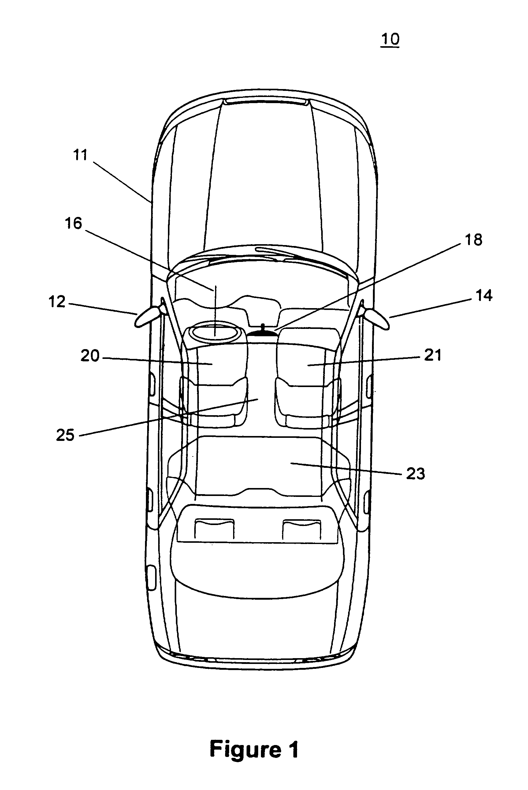
[0041]As illustrated in FIG. 1, passenger automobile 10 (which may be a sedan, a station-wagon, a sports car, a convertible, a minivan, a sports utility vehicle, a pick-up truck or a similar passenger carrying non-commercial, personal transportation automobile) includes an interior rearview mirror assembly 18 positioned within interior vehicle cabin 25. Interior vehicle cabin 25 further includes a steering wheel 16, a driver seat 20 positioned at steering wheel 16, a front passenger seat 21 adjacent to driver seat 20 in the front portion of cabin 25, and a rear passenger seat 23 in the rear portion of cabin 25. Automobile 10 further includes a driver-side exterior sideview mirror assembly 12 and a passenger-side exterior sideview mirror assembly 14, each adapted for attachment to opposing sides of automobile body 11, most preferably adjacent to the seating position of the driver seated in driver seat 20 for driver-side assembly 12 and adjacent to the front passenger seat 21 for pass...


PUM

PropertyMeasurementUnit
downward angleaaaaaaaaaa
outward angleaaaaaaaaaa

Abstract

An automobile exterior sideview mirror system includes an exterior sideview mirror assembly, which includes a reflective element assembly. The reflective element assembly includes a first reflective element having a unit magnification and a second reflective element having a curvature. The first reflective element and the second reflective element are supported at a support element. The mirror system preferably further includes an actuator, which is operable to adjust the orientation of the reflective element assembly. The second reflective element is disposed adjacent to and separate from the first reflective element when it is included in the exterior sideview mirror assembly. Further, a demarcation element is provided between the first reflective element and the second reflective element. A portion of the second reflective element adjacent the demarcation element has a front surface that is generally coplanar with the front surface of the first reflective element.

Description

[0001]This is a continuation application of U.S. patent application Ser. No. 09 / 745,172, filed Dec. 20, 2000, entitled EXTERIOR MIRROR PLANO-AUXILIARY REFLECTIVE ELEMENT ASSEMBLY, now U.S. Pat. No. 6,717,712, which is a continuation-in-part of U.S. patent application Ser. No. 09 / 478,315, filed Jan. 6, 2000, entitled “EXTERIOR MIRROR PLANO-AUXILIARY REFLECTIVE ELEMENT ASSEMBLY”, now U.S. Pat. No. 6,522,451, which are incorporated by reference herein in their entirety.TECHNICAL FIELD AND BACKGROUND OF THE INVENTION[0002]The present invention relates to exterior sideview mirror assemblies suitable for use on an automobile, and more specifically, to plano-auxiliary reflective element assemblies for use in automobile exterior sideview mirror assemblies.[0003]Automobiles are typically equipped with an interior rearview mirror assembly (adapted for providing a rearward field of view immediately rearward of the vehicle, typically principally in the road lane the vehicle is traveling in) and...

Claims


Application Information

Patent Timeline
Patent Type & Authority Patents(United States)
IPC IPC(8): G02F1/15B60R1/06G02B5/10G02B7/182B60R1/08
CPCB60R1/082Y10S248/90
Inventor LYNAM, NIALL RLINDAHL, JOHN OFUCHS, HAHNS Y
Owner DONNELLY CORP
Why Eureka
Try Eureka