Self-powered rotary optical aligning apparatus
- Summary
- Abstract
- Description
- Claims
- Application Information
AI Technical Summary
Benefits of technology
Problems solved by technology
Method used
Image
Examples
Embodiment Construction
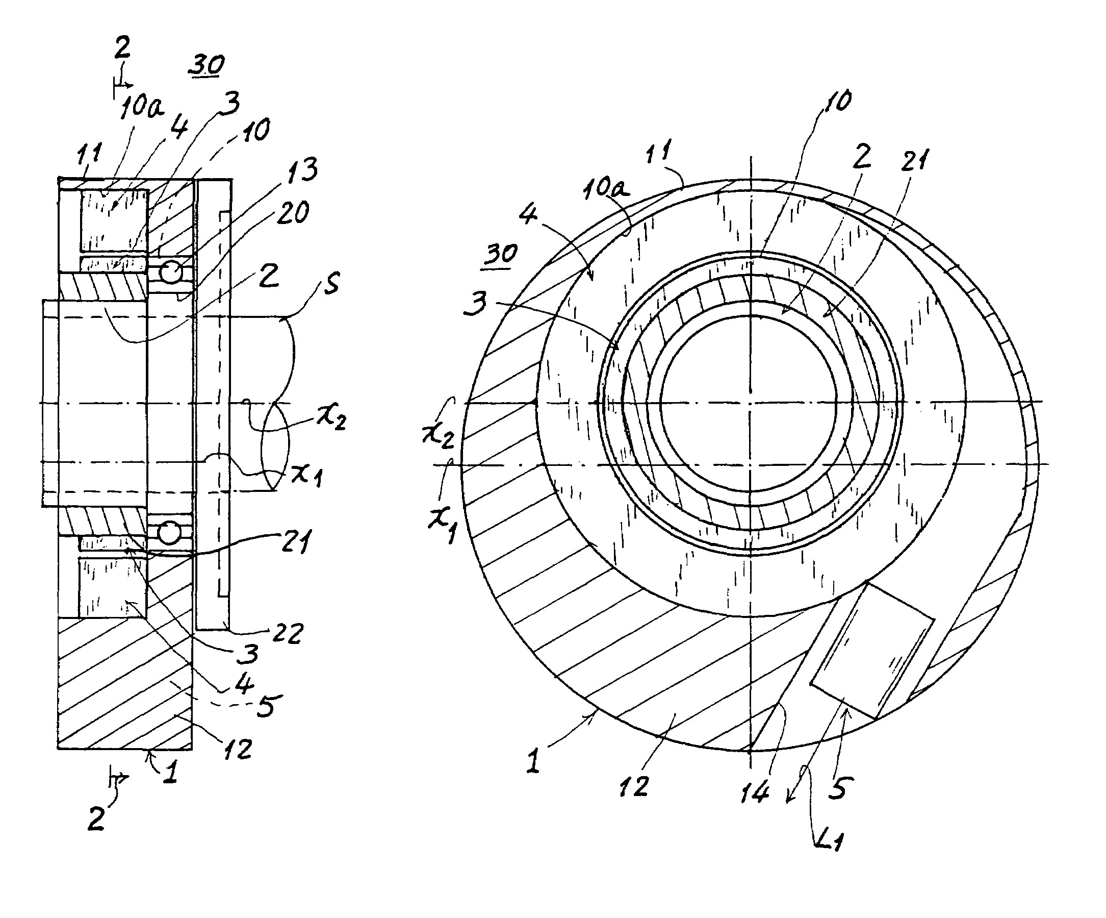
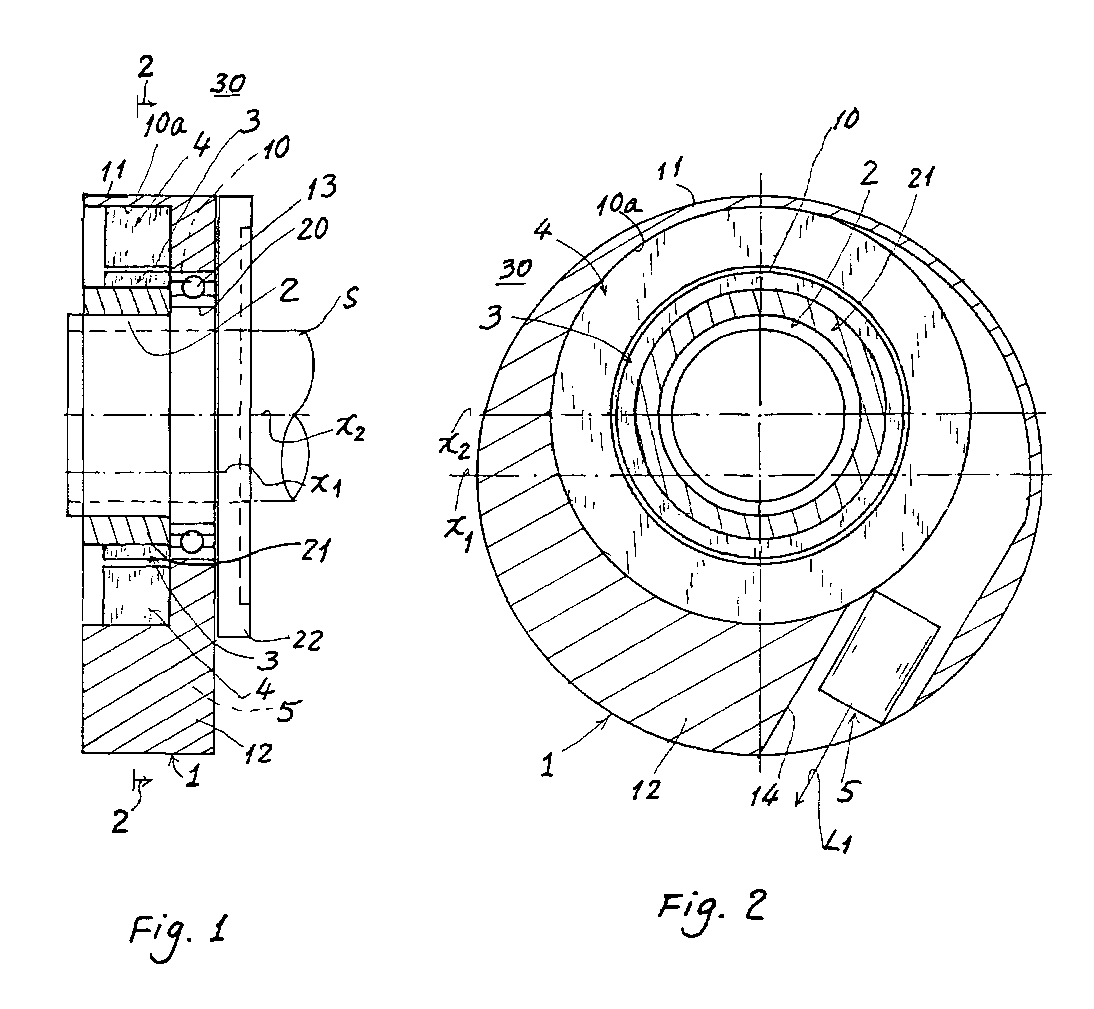
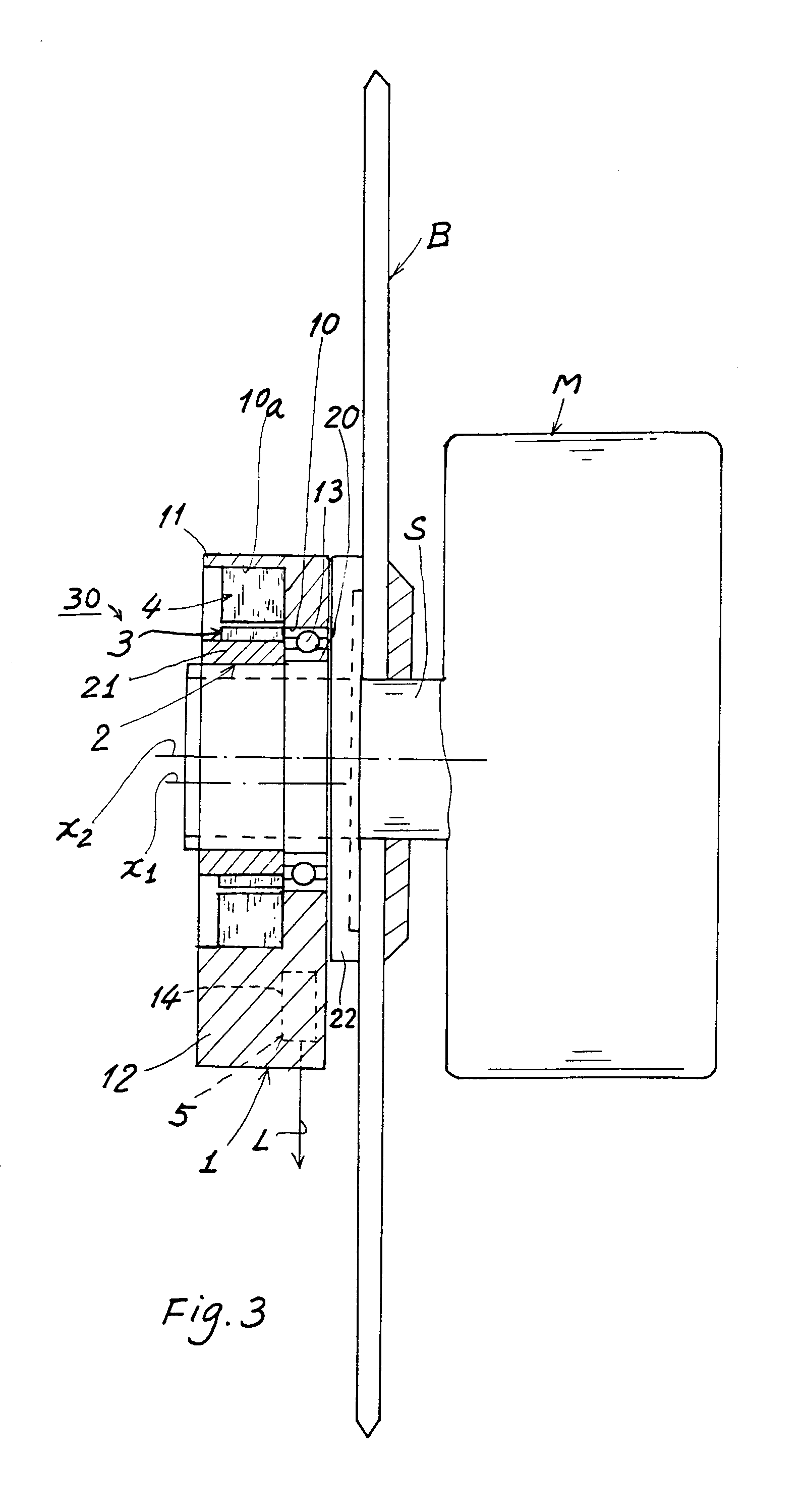
[0013]As shown in FIGS. 1˜3, an optical aligning apparatus of the present invention comprises: a pendulum disk 1; a sleeve 2 annularly secured on a shaft S of a driving motor M of a rotary machine such as a rotary saw B (FIG. 3); a power generator 30 including a multiple-pole magnet 3 concentrically formed on a collar 21 of the sleeve 2, and an electromagnetic coil 4 secured in the pendulum disk 1 and annularly rotatably disposed around the magnet 3; and an optical illuminator 5 mounted in a lower portion of the pendulum disk 1 and electrically connected to and powered by the power generator 30 when rotated for projecting an optical line to an object for alignment or marking purpose. The disk 1 is stationarily pendently hanged on the sleeve 2 and the shaft S.
[0014]The pendulum disk 1 includes: a disk center X1 which is eccentric to a shaft axis X2 of the shaft S of the driving motor M and the disk center X1 is positioned below the shaft axis X2 (FIG. 2), a circular hole 10 eccentric...
PUM
 Abstract
Description
Claims
Application Information
 - R&D
- Intellectual Property
- Life Sciences
- Materials
- Tech Scout
- Unparalleled Data Quality
- Higher Quality Content
- 60% Fewer Hallucinations
Browse by: Latest US Patents, China's latest patents, Technical Efficacy Thesaurus, Application Domain, Technology Topic, Popular Technical Reports.
© 2025 PatSnap. All rights reserved.Legal|Privacy policy|Modern Slavery Act Transparency Statement|Sitemap|About US| Contact US: help@patsnap.com


