
Personal water craft brake apparatus

a technology for water craft and brakes, which is applied in the field of water craft, can solve the problems of slowing down and stopping water craft, water craft do not have a rear discharge nozzle, etc., and achieves the effects of low manufacturing cost, convenient and efficient manufacturing and marketing, and durable and reliable construction

Inactive Publication Date: 2007-01-30
WILLIS CHARLES M
View PDF5 Cites 3 Cited by
  • Summary
  • Abstract
  • Description
  • Claims
  • Application Information

AI Technical Summary

Benefits of technology

[0025]It is another object of the present invention to provide a new and improved personal water craft brake apparatus which may be easily and efficiently manufactured and marketed.
[0026]It is a further object of the present invention to provide a new and improved personal water craft brake apparatus which is of durable and reliable construction.
[0027]An even further object of the present invention is to provide a new and improved personal water craft brake apparatus which is susceptible of a low cost of manufacture with regard to both materials and labor, and which accordingly is then susceptible of low prices of sale to the consuming public, thereby making such personal water craft brake apparatus available to the buying public.
[0029]Still another object of the present invention is to provide a new and improved personal water craft brake apparatus that does not require the employment of a rear discharge nozzle.
[0031]Even another object of the present invention is to provide a new and improved personal water craft brake apparatus that provides lift to the front of the water craft and drag to the stern of the water craft when the braking action takes place.

Problems solved by technology

As with all water craft, slowing down and stopping a water craft may be difficult to do, especially if the water craft is moving through the water at a relatively high speed.
If, however, most of the drag during braking takes place in front of the center of gravity, the water craft can tilt in a forward direction and can even flip over in the forward direction.
Some water craft, however, do not have a rear discharge nozzle.

Method used


Image

  • Personal water craft brake apparatus
  • Personal water craft brake apparatus
  • Personal water craft brake apparatus

Examples


Embodiment Construction

[0044]With reference to the drawings, a new and improved personal water craft brake apparatus embodying the principles and concepts of the present invention will be described.

[0045]With reference to the drawings, a new and improved personal water craft brake apparatus embodying the principles and concepts of the present invention will be described.

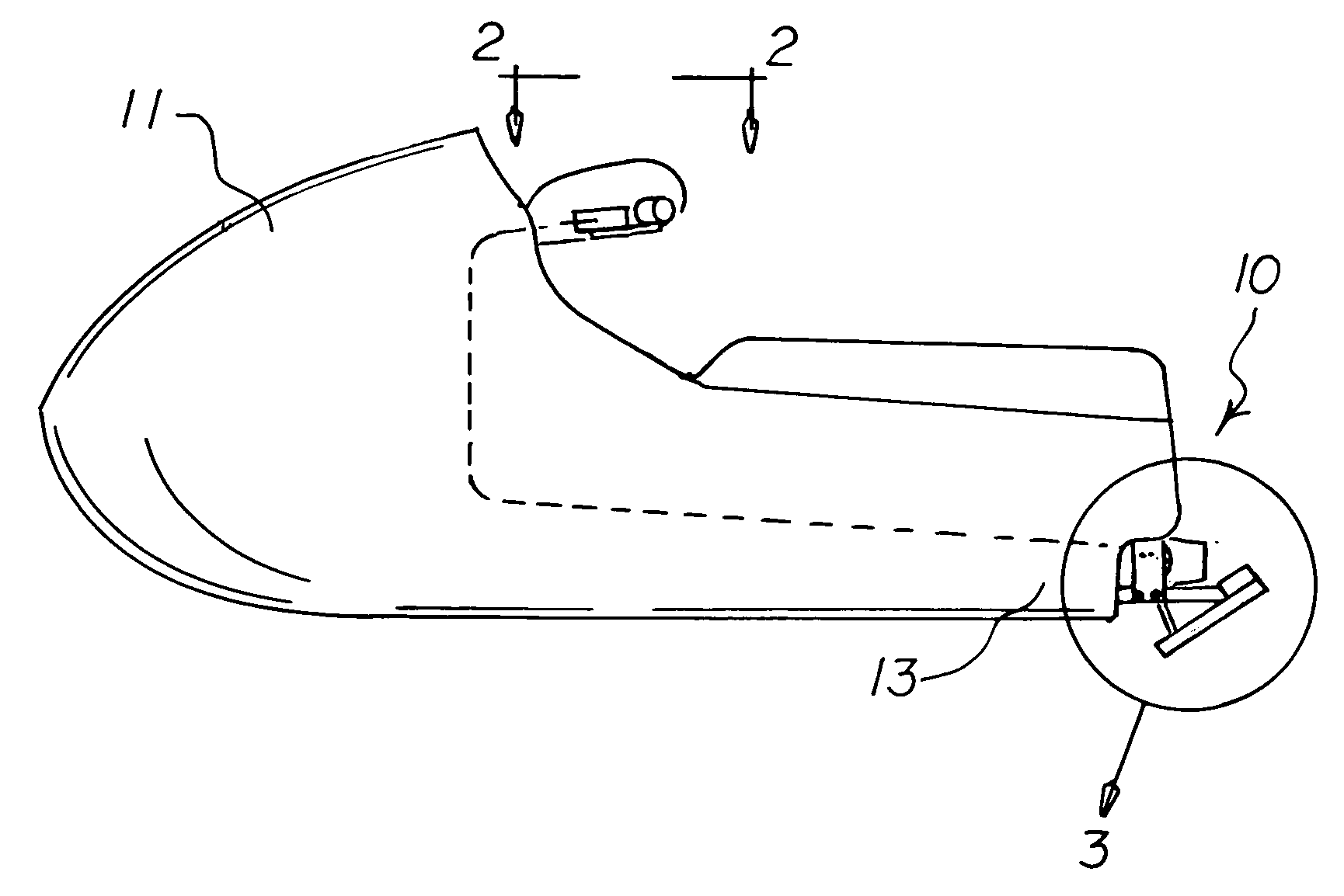
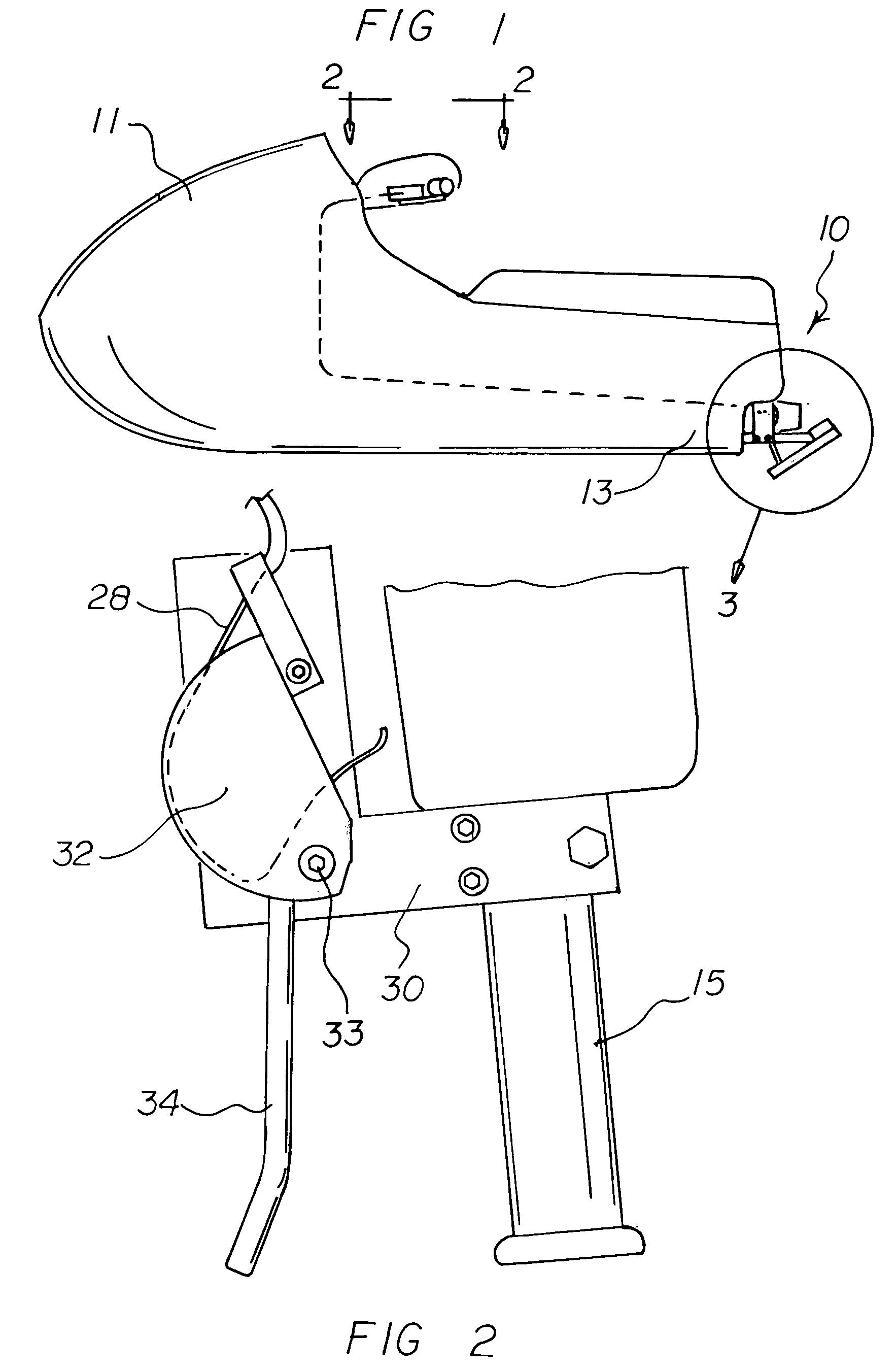
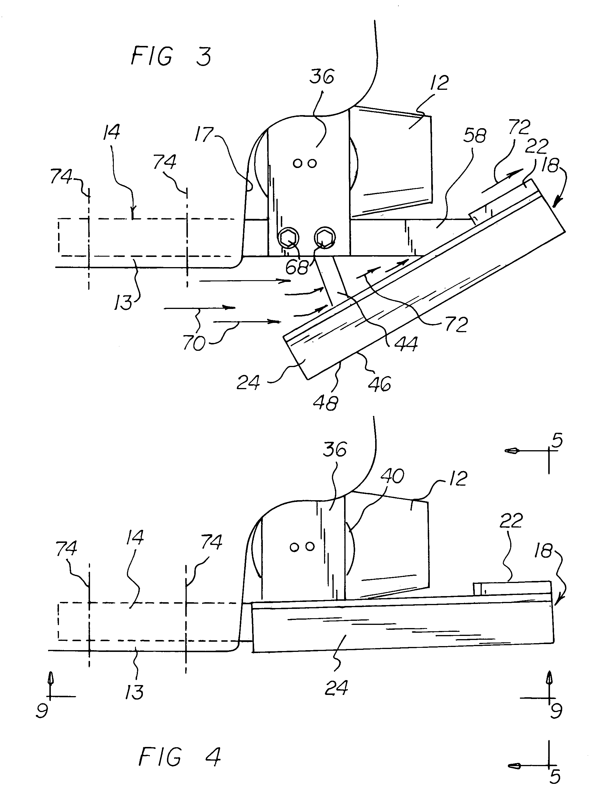
[0046]A brake apparatus 10 is provided for a water craft 11 which has a hull 13. The brake apparatus 10 includes a craft attachment unit 14 attached to the hull 13 of the water craft 11. A pair of transversely spaced, combined hinge assembly / hinge-to-plate connection brackets 22 is connected to the craft attachment unit 14. A brake plate 18 is connected to the combined hinge assembly / hinge-to-plate connection brackets 22. A brake plate control assembly is connected to the brake plate 18. The brake plate control assembly includes a brake cable 28 and a cable winder assembly which is connected between the brake cable 28 and the brake plate 1...


PUM


Abstract

A brake apparatus is provided for a water craft which has a hull. The brake apparatus includes a craft attachment unit attached to the hull of the water craft. A pair of combined hinge assembly / hinge-to-plate connection brackets is connected to the craft attachment unit. A brake plate is connected to the combined hinge assembly / hinge-to-plate connection brackets. A brake plate control assembly is connected to the brake plate. The brake plate control assembly includes a brake cable and a cable winder assembly which is connected between the brake cable and the brake plate for lifting and lowering the brake plate. The craft attachment unit is attached to a rear or stern portion of the water craft. Preferably, a return spring assembly is connected to the cable winder assembly. The return spring assembly returns the brake plate to a nonbraking mode or locked condition when braking action is no longer needed.

Description

BACKGROUND OF THE INVENTION[0001]1. Field of the Invention[0002]The present invention relates generally to water craft and, more particularly, to devices especially adapted for braking water craft.[0003]2. Description of the Prior Art[0004]A type of water craft that is very popular is a personal water craft. One type of personal water craft is known as a jet ski. With a jet ski, a stream of water emerges from a nozzle at the rear of the jet ski, and the stream of water provides thrust for the jet ski. As with all water craft, slowing down and stopping a water craft may be difficult to do, especially if the water craft is moving through the water at a relatively high speed. In this respect, throughout the years, a number of innovations have been developed relating to slowing down and stopping water craft, and the following U.S. patents are representative of some of those innovations: U.S. Pat. Nos. 2,994,290, 3,209,716, 5,193,478, 5,377,610, 5,493,990, and 5,988,091.[0005]It is noted...

Claims


Application Information

Patent Timeline
IPC IPC(8): B63H25/44
CPCB63H25/44
Inventor WILLIS, CHARLES M.
Owner WILLIS CHARLES M
Learn More