Cutting insert and milling cutter with such a cutting insert

a technology of cutting inserts and milling cutters, which is applied in the field of cutting inserts, can solve the problems of reducing the surface quality of the cutting edge with a decrease in the radius of the cutting edge, affecting the and the proposed requirement of an improved surface finish is practically impossible to achieve. , to achieve the effect of increasing the radius and high surface finish quality of the surfa

Inactive Publication Date: 2007-01-30
KENNAMETAL INC
View PDF11 Cites 36 Cited by
  • Summary
  • Abstract
  • Description
  • Claims
  • Application Information

AI Technical Summary

Benefits of technology

[0010]One possible object is to propose a cutting insert, particularly an indexable cutting insert, that permits, while avoiding the mentioned disadvantages, generation of a high quality surface finish of the work piece that is to be machined. Furthermore, a milling cutter, particularly a finish-machining cutter with such a cutting insert, is proposed that achieve a waviness depth or a profile depth in the work piece that is to be machined that is as low as possible, and thus achieves a particularly smooth surface quality of the surface that is to be machined.SUMMARY
[0023]In a further advantageous embodiment of the milling cutter, each plate seat provided for a cutting insert in the tool holder comprises, in addition to a support surface that is facing a corresponding base surface of the cutting insert and a contact surface that is facing a corresponding lateral surface of the cutting index, a take-up or receiving opening for take-up or receiving of an abutment pin that serves as axial abutment for the cutting insert. Since this abutment pin is not mounted until after the production of the plate seat, the support surface and the contact surface of the plate seat can be machined simultaneously in one operating step. This makes it possible that a precision of the planar extent of 10 μm can be achieved.
[0024]The advantages obtained with the invention reside primarily therein that particularly due to the combination of the off-centered bulge of the conically shaped surface portion of the respective lateral surface of the cutting insert—and with this, due to the bulged cutting edge with a decentralized disposed maximum of a bulge or summit point—as well as the arrangement of the cutting insert within the tool holder anteriorly of its 0 degree center line, due to a thereby caused increased radius, serves to achieve a particularly high surface finish quality of the surface of a work piece that is to be machined. Particularly, with such a tool, used as a finish-machining milling cutter, remaining waviness depths or profile depths are achievable that are lower by a factor of 2 as compared to hitherto known finish-machining milling cutters for machining work piece surfaces.

Problems solved by technology

Of disadvantage are hereby the sensitivity with regard to angle errors during positioning of this linear cutting edge with respect to the work piece surface, such that a preferred approach that resides in use of only an end portion of the cutting edge at the surface that is to be machined is practically unavoidable and, accordingly, the posed requirement of an improved surface finish is practically not attainable.
Such a cutting edge that is circular or ellipsoidal in reference to the surface to be machined, however, due to values of curvature that are uniform or uniformly increasing commencing from the center of the cutting edge in the direction of the two cutting edge ends, entails undesirable small errors of tolerances with reference to angle errors with a cutting body radius that is increasing.
In the case of a cutting edge that is configured to be circularly curved, furthermore, the diminishing of surface quality with a decrease in the radius of the cutting edge is of particular detriment.
Of disadvantage in such position fixing of the cutting insert with an unchanging cutting edge position is the requirement of a very precise tool carrier for the cutting insert.
Pursuantly, in the case of a cutting insert connection with a subsequent shift in position of the cutting edge, an increased susceptibility of the entire system with respect to shifting of the position of the cutting edge by external circumstances is of disadvantage.

Method used


Image

  • Cutting insert and milling cutter with such a cutting insert
  • Cutting insert and milling cutter with such a cutting insert
  • Cutting insert and milling cutter with such a cutting insert

Examples


Embodiment Construction

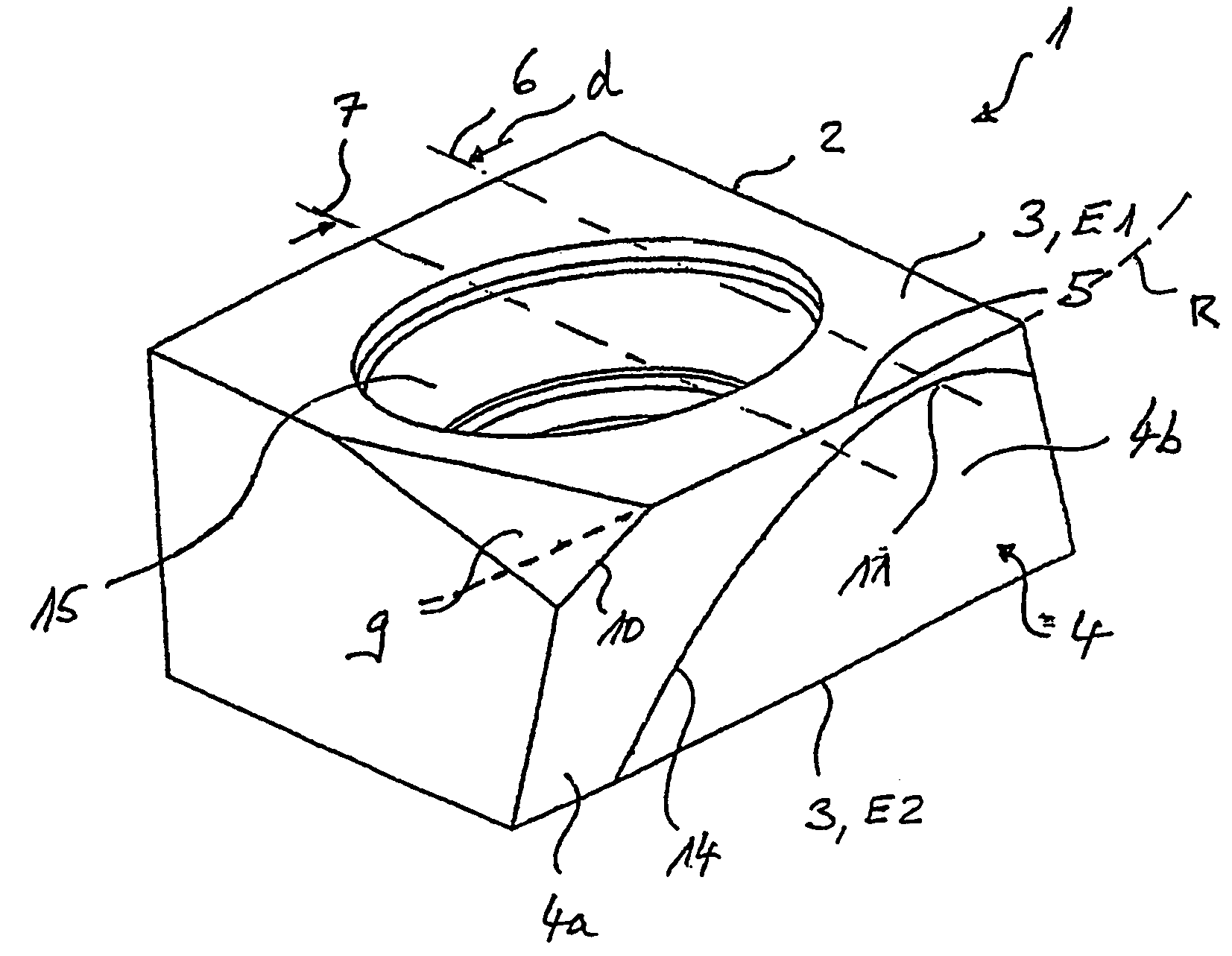
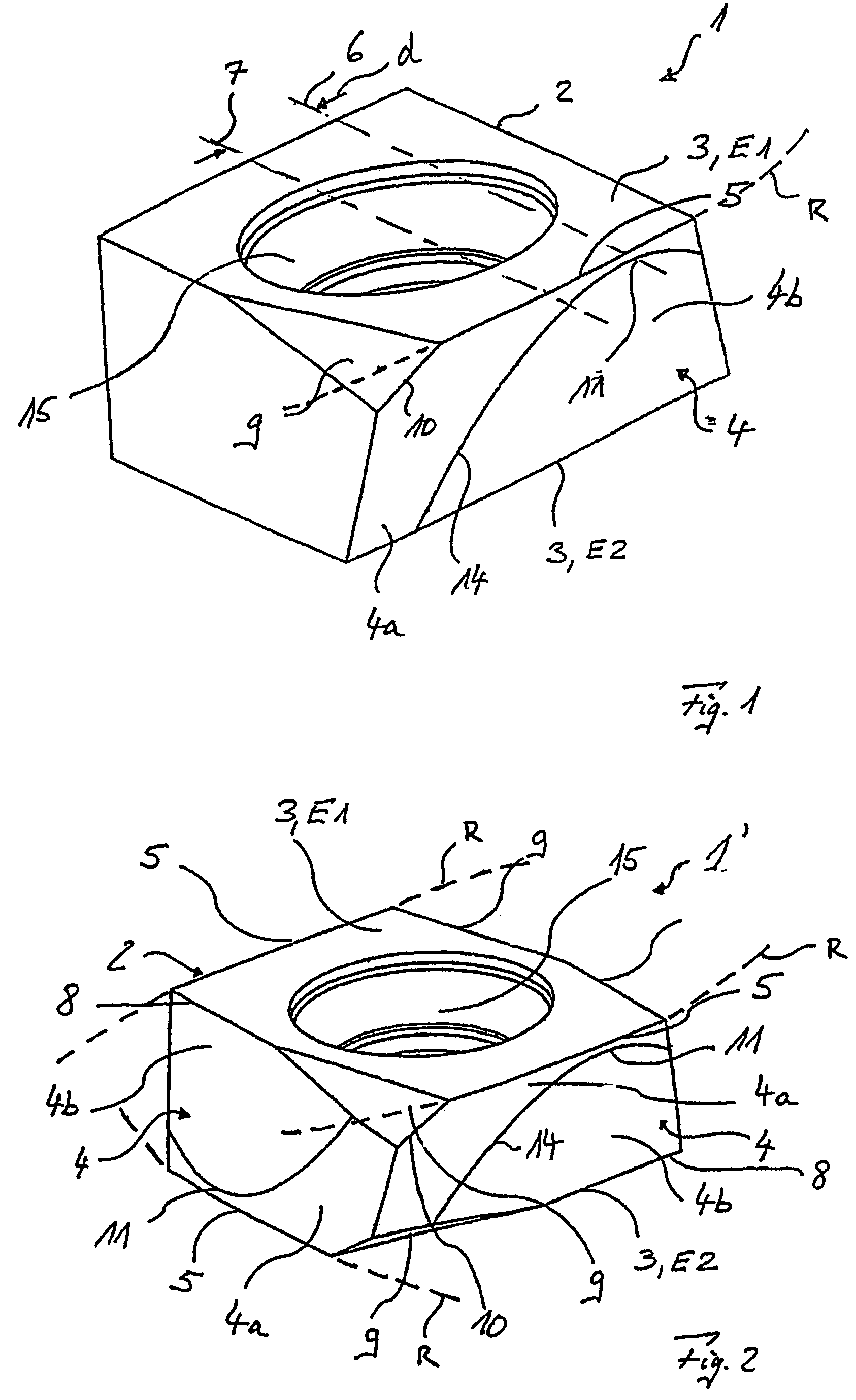
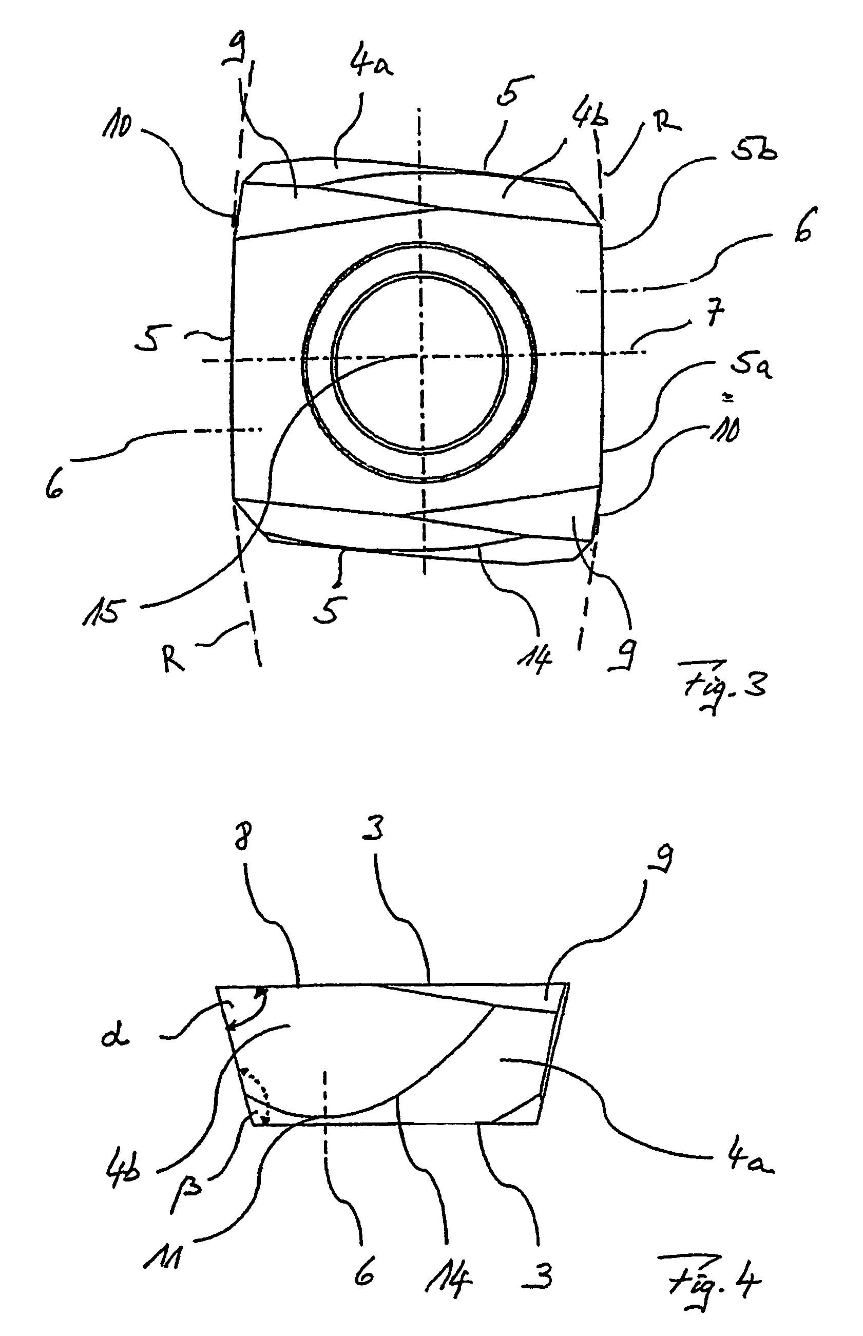
[0039]The cutting insert 1 illustrated in FIG. 1 comprises a base body 2 with two base surfaces 3 that are disposed in plate planes E1 and E2 that are disposed oppositely with respect to one another. The cutting insert 1 also comprises a lateral surface 4 with a cone-mantle-shaped surface portion 4a and a planar surface portion 4b. The cone-mantle-shaped surface portion 4a, as well as the base surface 3 that is facing it are disposed with respect to one another under an acute angle α (FIG. 4) and form a cutting edge 5. The planar surface portion 4b is disposed at an obtuse angle β (FIG. 4 with the oppositely disposed base surface 3.

[0040]The cutting edge 5 has a curved or arcuate course with a very large radius of curvature, R, that is disposed within the plane E1 of the base surface 3, with off-centered—and, accordingly, asymmetrical—bulging of the cone-mantle-shaped surface portion 4a. Thereby, the cone axis 6 that is disposed in the plate plane E1 of the cone-mantle-shaped surfac...


PUM


Abstract

A cutting insert 1, 1′, comprising opposite insert planes E1, E2 of a base 2 of one base area 3 wherein a conical surface section 4a of a lateral face 4 and the base area 3 facing the same form an acute angle alpha while forming a cutting edge 5, while a planar surface section 4b of the same lateral face 4 forms an obtuse angle beta with the opposite base area 3. The cone axis 6 of the conical surface area 4a lying in the insert plane E1, E2 runs off-set in parallel to the center insert axis 7 lying in the same insert plane E1, E2 while forming an off-center arcuate profile of the cutting edge 5. A milling cutter 17 comprising a number of such cutting inserts 1, 1′ is characterized in that a cutting insert 1, 1′ preferably disposed on the periphery of the center line M of a tool support 16 is off-set from the center line M by an angle phi equal to 5±3 degrees.

Description

CONTINUING APPLICATION DATA[0001]This application is a Continuation-In-Part application of International Patent Application No. PCT / EP02 / 09938, filed on Sep. 5, 2002, which claims priority from Federal Republic of Germany Patent Application No. 201 14 783.1, filed on Sep. 6, 2001. International Patent Application No. PCT / EP02 / 09938 was pending as of the filing date of this application. The United States was an elected state in International Patent Application No. PCT / EP02 / 09938.BACKGROUND[0002]1. Technical Field[0003]This application relates to a cutting insert having opposite plate planes of a base body with respectively one base surface for each plane, as well as at least one lateral surface. This application relates furthermore to a milling cutter with such a cutting insert. The term cutting insert is particularly to mean an indexable cutting insert and the term milling cutter is particularly to mean a milling cutter for producing or machining finished surfaces.[0004]2. Backgroun...

Claims


Application Information

Patent Timeline
Patent Type & Authority Patents(United States)
IPC IPC(8): E21B10/633B26D1/12E21B10/43B23C5/20B23C5/22
CPCB23C5/207B23C5/2221B23C2200/0416B23C2200/085B23C2200/123B23C2200/125Y10T407/1924B23C2200/205B23C2200/367B23C2210/168B23C2250/16Y10T407/1964B23C2200/203B23C5/2213B23C5/202
Inventor SCHUFFENHAUER, MICHAELKRANZ, STEFFENBOGUTH, WERNER
Owner KENNAMETAL INC
Why Eureka
Try Eureka