High pressure tank

a technology of high pressure tank and liner, which is applied in the direction of container discharge methods, separation processes, bridges, etc., can solve the problems of gas leakage, failure of local sealing, and separation of brazed portions, so as to achieve reliable sealing of the separated portions of the liner

Inactive Publication Date: 2007-01-30
TOYOTA IND CORP +1
View PDF12 Cites 34 Cited by
  • Summary
  • Abstract
  • Description
  • Claims
  • Application Information

AI Technical Summary

Benefits of technology

[0009]Accordingly, it is an objective of the present invention to provide a high pressure tank capable of reliably sealing the separated portions of a liner.

Problems solved by technology

However, the re-heat treatment may cause separation of the brazed portions or a failure in locally disposed seals.
It is however difficult to lay out reinforced fibers in the direction parallel to the axial direction of the hydrogen tank.
Because helical winding provides lower strength against radial-directional force relative to hoop winding, however, gas leakage occurs.

Method used


Image

  • High pressure tank
  • High pressure tank
  • High pressure tank

Examples


first embodiment

[0034]the present invention is described below with reference to FIGS. 1 to 4.

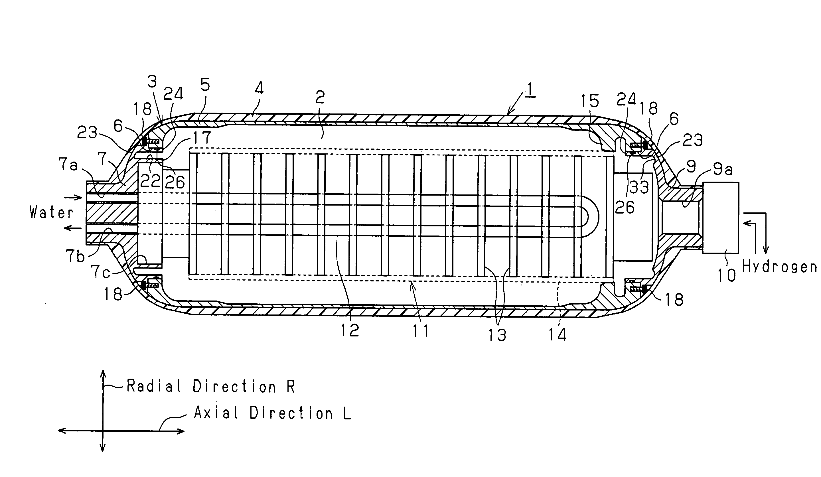
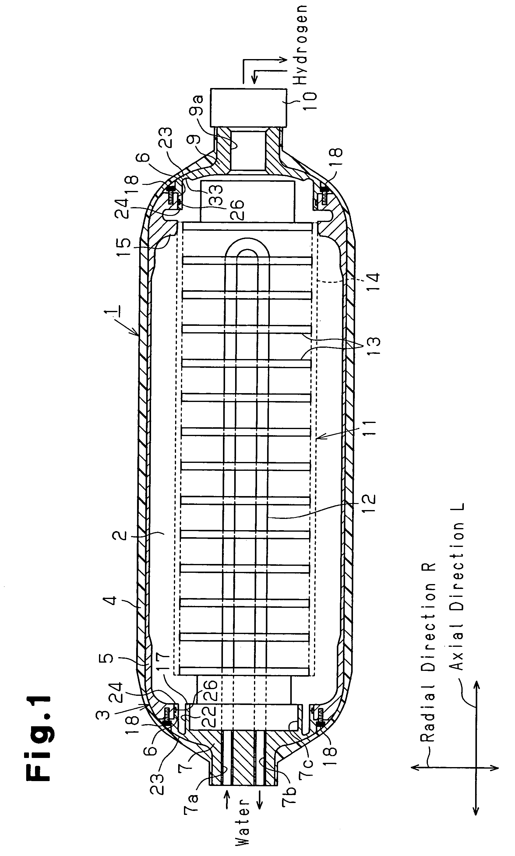
[0035]FIG. 1 is an exemplary cross-sectional view of a hydrogen tank 1. The hydrogen tank 1 for use as a high pressure tank has an elongated cylindrical shape and has a liner 3 inside. A retaining chamber 2 is defined in the liner 3. The retaining chamber 2 is filled with hydrogen as the gas under high pressure. A lot of hydrogen can be filled inside the retaining chamber 2 by setting the interior of the retaining chamber 2 to a relatively high pressure. In the case where the pressure in the retaining chamber 2 is set to 25 Mpa, for instance, hydrogen about 250 times as great as that of air can be filled. One of the ends of the hydrogen tank 1 is where hydrogen comes enters and exits is the distal end (right-hand side in FIG. 1), and the opposite end is the proximal end (left-hand side in FIG. 1).

[0036]The liner 3 of the hydrogen tank 1 has an approximately cylindrical shape and a high-strength carbon fibe...

fourth embodiment

[0094]Even when the internal pressure of the liner 3 becomes high in the hydrogen tank 111 of the fourth embodiment, expansion of the opening portions 40a and 40b is restrained by the reinforcing portions 147.

[0095]The fourth embodiment has the following advantages in addition to the advantages of the third embodiment in FIGS. 7 and 8.

[0096]The annular groove 48 is open outward in the axial direction of the liner 3. Unlike in the case of the embodiment in FIGS. 7 and 8 which is provided with the annular groove 46 open outward in the radial direction of the liner 3, the reinforcing portion 147 can be attached easily in the annular groove 48.

[0097]The reinforcing portion 147 is formed by punching out a metal plate by pressing. The fabrication of the reinforcing portion 147 is therefore easier than a reinforcing portion formed of a fiber reinforced resin having a bundle of fibers wound annularly as reinforced fibers.

[0098]Stainless steel is used as the material for the reinforcing port...


PUM

PropertyMeasurementUnit
pressureaaaaaaaaaa
diameteraaaaaaaaaa
hollow barrel shapeaaaaaaaaaa

Abstract

A high pressure tank has a cylindrical liner and a fiber reinforced plastic layer which covers the outer surface of the liner. At least one end of the liner is separable. The liner includes a cylindrical liner body and a lid. An O-ring is located between the contact surfaces of the liner body and the lid in the circumferential direction. Each contact surface has a seal surface which contacts the O-ring. One of the liner body and the lid has a deformable portion which deforms toward the seal surfaces. The structure can securely seal the separated portions of the liner when the high pressure tank is in a high pressure state.

Description

BACKGROUND OF THE INVENTION[0001]The present invention relates to a high pressure tank having a hollow liner and a fiber reinforced resin layer which covers the outer surface of the liner.[0002]Awareness of the need to restrain global warming has been increasing recently. Particularly, developments in fuel-cell electric vehicles and hydrogen-powered vehicles have been made progressively for the purpose of reducing carbon dioxide which is emitted from vehicles. These vehicles induce power by electrochemical reaction of hydrogen and oxygen and supply the power to motors to generate drive force. A hydrogen tank is used as a hydrogen source and is filled with hydrogen at high pressure.[0003]FIG. 16 is a cross-sectional view of a hydrogen tank 51 for use as a high pressure tank disclosed in Japanese Laid-Open Patent Publication No. 2002-181295. The hydrogen tank 51 has a liner 52 having a hollow barrel shape. The liner 52 is made of a material which ensures an airtight condition (e.g., h...

Claims


Application Information

Patent Timeline
Patent Type & Authority Patents(United States)
IPC IPC(8): F17C13/06F17C1/00F17C11/00
CPCF17C1/00F17C11/005Y02E60/321F17C2201/0109F17C2201/035F17C2201/054F17C2201/056F17C2203/0604F17C2203/0621F17C2203/0636F17C2203/0639F17C2203/0643F17C2203/0646F17C2203/0648F17C2203/0658F17C2203/066F17C2203/0665F17C2203/067F17C2205/0305F17C2205/0323F17C2209/2154F17C2209/221F17C2209/228F17C2221/012F17C2221/014F17C2221/033F17C2223/0123F17C2223/035F17C2223/036F17C2227/0316F17C2227/0348F17C2227/0372F17C2260/011F17C2260/012F17C2260/018F17C2260/025F17C2260/036F17C2265/066F17C2270/0168F17C2270/0184F17C2270/0763Y02E60/32E01D19/00F16B13/128F16B2013/006
Inventor KUBO, HIDEHITOTSUZUKI, MAKOTOTOH, KEIJIKUMANO, AKIKOMORI, DAIGOROKIMBARA, MASAHIKO
Owner TOYOTA IND CORP
Why Eureka
Try Eureka